
Behind the plug: What really happens when your EV talks to the charger
In this Part 2 of "Behind the Plug", we'll start to cover the communication protocols (aka "languages") used to facilitate an interoperable, seamless charging experience.

In Part 1 of this “Behind the plug” series (Who’s who in the EV charging ecosystem), we lifted the curtain on the EV charging world and discovered just how many players are working behind the scenes to deliver a simple outcome: your car gets the energy it needs.
But the more actors involved, the more chances there are for something to go wrong. A single weak link in the chain – whether it’s the EV, the charger, the network operator’s Charge Point Management System (CPMS), a roaming hub, or a payment provider – can derail the entire experience. No energy. Frustrated driver. Lost revenue.
To avoid that, every system in this chain needs to speak the same language. That language is defined by communication protocols.
You might think: “What’s there to talk about? I want my car to be fully charged asap, here are my payment details, plug in and done!”
In reality, delivering electricity to your EV is a carefully choreographed digital conversation. So let’s break down what information needs to flow between all these components, and how communication protocols make the magic work.
Today, we focus on how the EV and the charger talk to each other. In the next edition, we’ll venture deeper into the protocol jungle and explore the rest of the ecosystem.
What are they even talking about?
Once an EV plugs into a charger, the real work begins. Not through sparks and cables, but through data. Before a single electron flows, the car and the charger start exchanging information like two strangers figuring out how to dance together.
The EV says things like:
How much energy I need
My max charge power
What voltages and currents I can safely handle
When I plan to leave – so no need to rush, or please do rush!
What energy contract I want to use at this location (if Plug & Charge is enabled)
In return, the charger reports to the EV:
What power it can deliver right now, and how this may change over the next hours
Confirmation that the driver is actually allowed to charge here
Whether all safety checks are complete to start charging
Then there’s the wider ecosystem. The charger usually not acting alone, it’s constantly checking in with the Charge Point Management System (CPMS), sending operational and health status updates, keeping track of the energy delivered to the EV, and receiving smart-charging instructions that align power delivery with grid needs.
And further down the chain, the CPMS coordinates with a Mobility Service Provider (MSP) or roaming hub to sort out:
Where the charger is located and whether it’s available for energy delivery
Who the driver is and whether he or she is allowed to charge
Which price to apply and how the session will be billed
So while you’re casually plugging in and walking away, there’s a multi-party negotiation unfolding in seconds. Everyone in this chain – the EV, the charger, the backend systems, the payment platforms – must quickly agree on what’s happening, what’s allowed, and what comes next.
That’s the conversation. Next, we’ll explore the languages they use to have it: the communication protocols that intend to keep charging simple for drivers. But boy can they be incredibly complex under the hood.
EV to charger communication protocols
If you’ve ever tried to make sense of all the acronyms flying around in the EV charging world – OCPP, OCPI, OICP, OCHP, OPNC – you’re not alone.
The list of communication protocols can make your head spin (and yes, the fact that so many start with O and include a C and a P is not lost on anyone). I guess protocol nerds are not the most creative bunch of people when it comes to naming…
Let’s start with the EV itself and follow the data trail outward, step by step.

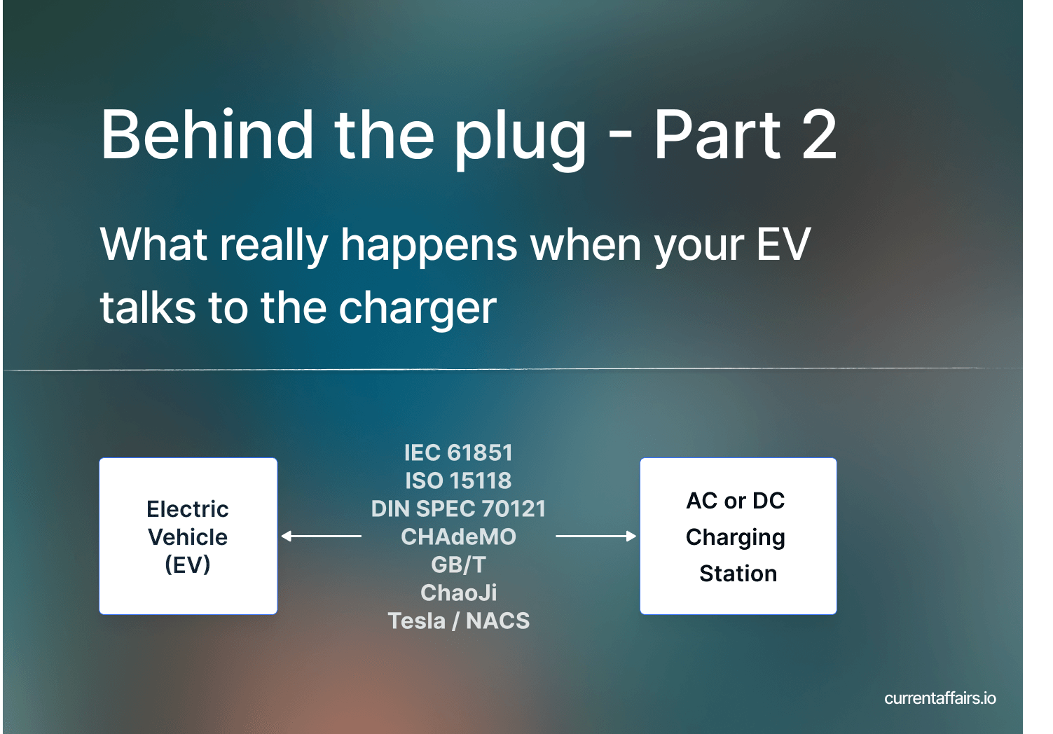
When an EV connects to a charging station, they need a shared language to coordinate the flow of energy. This can happen in one of two ways:
through analogue signalling or digital communication.
IEC 61851
The IEC 61851 standard governs the analogue communication between the EV and the charger. It defines the basic safety mechanisms that ensure power only flows when it’s safe, i.e. when the vehicle is stationary and correctly connected.
When the charging cable is plugged in, the station sends what is called a pulse width modulation (PWM) signal along the control pilot (CP) line of the charging cable. The EV reads the duty cycle of this PWM signal (expressed as a percentage) to determine how much current it’s allowed to draw.
If you’re thinking “duty what now?”, you’re not alone. The first time I saw the term, I assumed it was one of those insider phrases electricians knowingly toss around over a bottle of cold beer. In reality, the duty cycle is simply the ratio of how long a signal is ON vs. OFF during each tiny pulse. It’s expressed as a percentage, and the higher that percentage, the more current the EV is allowed to draw. Think of it like the charger saying: “I’m 53% ‘on’, feel free to take up to 32 amps.”
A duty cycle between 10% and 96% represents a theoretical charging range from 6 A to 80 A per phase, though in practice, most AC chargers are limited to 11 kW (16 A) or 22 kW (32 A) per phase.
A phase is basically one live wire carrying power in a rhythm (a sine wave), like a lane on an electrical highway; using three phases means three live wires working together to deliver more power at once, which charges your car faster.
The image below illustrates the concept of this analogue “communication” between the EV and the charger on the Control Pilot wire of the charging cable. This example is specifically relevant for slower AC charging, DC charging works slightly different. (Hold on, you eager beaver, we’ll get to that in a minute. )
 and duty cycles")
Let’s run through how the Control Pilot signal guides the charging process, as defined in IEC 61851:
Charger waiting (State A: +12 V)
No car plugged in
Control Pilot sits at a steady +12 volts
Meaning: “I’m here and ready, but no vehicle connected”
Car plugs in → voltage drops (State B: +9 V)
The EV adds a resistor to ground when inserted
Voltage drops from +12 V → +9 V
Meaning: “A vehicle is present and communication can start”
Charger begins sending a 1 kHz square-wave (the PWM signal)
Positive part of the wave encodes max current available
Car requests charging → clipped signal (State C: +6 V)
The EV changes the resistance again to show it is ready to draw power
The positive peak is clipped to +6 V
Meaning: “Ready to charge” → “Charging in progress”
The width of the positive pulses (duty cycle) tells the EV how many amps it may pull
The -12 V portion keeps confirming grounding and line integrity
Charging stops → signal returns
EV stops power draw → positive peak goes back to +9 V
Driver unplugs → solid +12 V again
Meaning: “Session over, no EV connected”
Beyond States A to C, IEC 61851 also defines additional safety-related states:
State D: Vehicle connected and charging possible, but ventilation required (not used anymore, was only relevant for old lead-acid batteries)
State E: Supply fault, Control Pilot power lost, charging disabled
State F: Ground fault, PE issue detected, charging prohibited
Does that make sense? Hope so. If not, let me know.
Now, you might think: “What’s this ‘Control Pilot’ wire he’s talking about?”
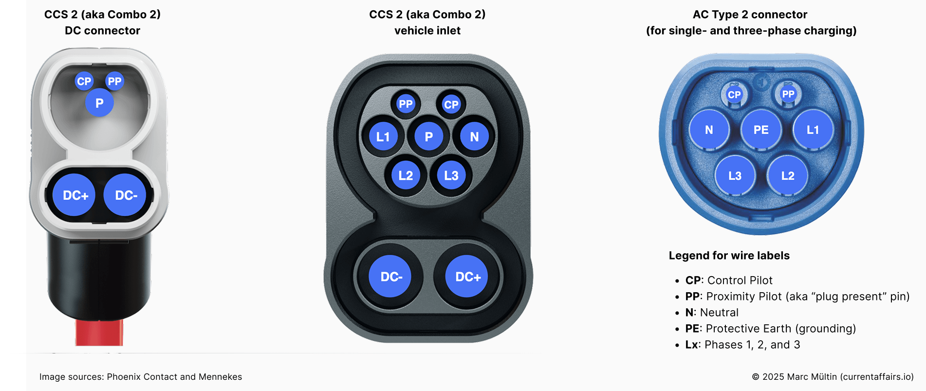
Great question, and a perfect moment to quickly decode what’s actually hiding inside these charging plugs. Below you’ll see the CCS 2 connector used for DC fast charging (left), the matching vehicle inlet (middle), and the familiar Type 2 AC plug (right). You’ve probably used these countless times without thinking about what each pin does. But after this, you’ll know exactly how they work and can impress the next EV driver you meet at the charger.
What all those pins actually do (Type 2 & CCS2 connectors)
Every pin has a very specific job:
L1, L2, L3: the power lanes
These are the three phases that carry the actual AC charging power. The car can use one of them (single-phase) or all three at once (three-phase) to charge faster.N: Neutral
Completes the electrical AC circuit, working together with the phases.PE: Protective Earth (ground)
A safety connection to the ground. If something ever goes wrong, this gives the electricity a safe path away from you and the car.CP: Control Pilot
The communication lifeline between car and charger. It tells the EV how much current it’s allowed to draw and whether charging is permitted. It’s also how the system detects when the plug is inserted or removed.PP: Proximity Pilot
A simple but important safety pin: it detects that a cable is plugged in and prevents the car from driving away with the cable still attached. It also tells the charger how thick the cable is, and therefore how much current the cable can safely handle.
By the way, CCS stands for Combined Charging System – “combined” because it merges the Type 2 AC interface at the top with the two larger DC+ and DC– pins below for fast DC charging. Type 2 and CCS2 are the standard in e.g. Europe, the UK, Australia, and India, while the slightly different Type 1 / CCS1 interface (built around a single-phase AC design) dominates in the U.S., Canada, and Japan.
Since its introduction in the early 2010s, CCS has been adopted as the de facto global standard for DC fast charging in Europe, North America, and much of the world. It’s supported by virtually all major automakers and infrastructure providers and governed by the Charging Interface Initiative (CharIN) e.V. Have a look at their website to learn more about their initiatives, members, white papers and organised industry events.
I could happily keep diving into the nuances of global charging connectors, but that would lead us deep down the hardware rabbit hole. And this article is really about communication protocols. So let’s shift gears from plugs and pins to the digital language that makes EV charging smart.
ISO 15118 and DIN SPEC 70121
After mastering the electrical handshake, the industry needed something smarter. A way for the car and charger to actually talk. That’s where ISO 15118 and DIN SPEC 70121 step in. CCS builds on the basic safety handshake defined in IEC 61851, and adds ISO 15118 and DIN SPEC 70121 on top of it to enable digital communication.
These digital communication standards run over Power Line Communication (PLC), using the same Control Pilot wire that already handles the PWM signal. In other words: without adding any extra wires, the EV and charging station can now exchange real data, from basic status updates to fully automated Plug & Charge experiences.
IEC 61851 dictates that if a digital protocol is used, the duty cycle should drop to 5%, signalling the start of “high-level communication”. From that point on, it’s all data: bits and bytes defining authentication credentials, charging parameters, and energy flow.
DIN SPEC 70121 is focused on DC charging and was originally conceived as a temporary bridge when it was first released in 2012, until ISO 15118 was finalised in 2014. But as the saying goes, nothing is as permanent as a temporary solution. It’s still widely used today.
ISO 15118, by contrast, supports both AC and DC charging and forms the foundation for modern innovations like Plug & Charge, Vehicle-to-Grid (V2G), and solid cybersecurity measures, which we’ll explore more in future articles.
It’s also worth noting that ISO 15118 itself has evolved: from the foundational ISO 15118-2 published in 2014 (covering AC and DC charging) to the newer ISO 15118-20 published in 2022, which extends capabilities such as bi-directional power flow (enabling your car to power your home or stabilise the grid when needed and getting paid for it), better support for multi-contract handling for Plug & Charge, and advanced cybersecurity enhancements. I’ll unpack these differences and what they mean for CPOs, OEMs, and utilities in future posts.
At its core, ISO 15118-2 upgrades charging from a simple power delivery experience to a smart, secure, and fully automated one. For drivers, it enables Plug & Charge: you just plug in, and the car and charger authenticate each other automatically, no apps or RFID cards needed. This magic is powered by digital certificates and cryptographic signatures that ensure both sides can truly trust who they’re talking to. For charge point operators and energy companies, it unlocks smart charging features like scheduling, price-responsive charging, and load balancing to protect the grid and reduce costs.
I literally wrote the book on this – the ISO 15118 Manual back in 2017 – so believe me, there’s a lot more to explore. We’ll start with the essentials here, and save the deeper magic for upcoming articles.
CHAdeMO, GB/T, ChaoJi, and Tesla / NACS
The Combined Charging System (CCS) has probably the biggest adoption worldwide, but it’s not the only DC-based charging system.
CHAdeMO, for example, is a Japanese DC charging and communication standard that came to market with early Nissan and Mitsubishi vehicles. It also enabled some of the world’s first vehicle-to-grid (V2G) trials, thanks to its built-in bi-directional power flow capability. While many stations still support CHAdeMO, its relevance outside Japan is fading since Nissan’s 2020 decision to move to CCS for the European and U.S. markets.
GB/T is China’s national DC charging and communication standard, used exclusively for EVs and chargers sold within China. Like CHAdeMO, it relies on CAN bus communication rather than PLC and therefore does not use PWM signalling.
ChaoJi (also known as CHAdeMO 3.0) is the next-generation DC charging system jointly developed by the CHAdeMO Association and the China Electricity Council (CEC). It supports ultra-high-power charging (up to ~900 kW) and is designed for backward compatibility with both CHAdeMO and GB/T connectors. ChaoJi still uses CAN-based communication but represents a more coordinated step toward a globally harmonised DC standard.
Tesla’s North American Charging Standard (NACS) – now formalised as the SAE J3400 standard – has rapidly become the dominant connector type in North America. Unlike Tesla’s original proprietary CAN-based setup, J3400 uses Power Line Communication and supports ISO 15118 / DIN 70121 messaging. This makes it technically compatible with Plug & Charge, aligning it with CCS communication layers and paving the way for full interoperability as automakers and networks adopt ISO 15118-compliant firmware and PKI integration.
That’s all folks. You now have a solid overview of the charging systems used around the world, the communication protocols involved, and the capabilities they unlock.
If an acronym ever slips your mind, bookmark the Acronym Survival Guide. Future you will be grateful.
Next week, in Part 3 of the Behind the Plug series, we’ll explore the communication protocols that connect the rest of the e-mobility ecosystem. The ones working behind the scenes beyond the plug. Stay tuned!