
From black box to glass box: Unlocking full charger visibility with OCPP 2.0.1 Device Model
A deep dive into the protocol feature every CPO should understand – and most don't – that makes chargers observable, configurable, and ready to scale

You want to know when any charging station in your network exceeds 55°C internal temperature – before it triggers a thermal shutdown. Under OCPP 1.6, you can’t. The protocol has no mechanism for you to define monitoring thresholds. You receive what the station decides to send, when it decides to send it. If the manufacturer didn’t build in that specific alert, you’re waiting for the fault notification after the fact.
This is one example of a broader limitation. OCPP 1.6 gives operators a keyhole view into charging stations: transaction events, status changes, periodic meter values. What it doesn’t provide is a way to ask questions the protocol designers didn’t anticipate, or to configure monitoring based on what matters to your operation rather than what the manufacturer deemed important.
OCPP 2.0.1 introduces the Device Model concept: a structured representation of charging station internals that operators can query, configure, and monitor on their own terms. If OCPP 1.6 gave you a check engine light, the Device Model gives you the full OBD-II diagnostic port. It's the difference between scaling a charging network and being scaled by it.
From key-value chaos to structured intelligence
Let’s start with what we’re leaving behind.
OCPP 1.6 stores charging station configuration as a flat list of key-value pairs. Think of it as a dictionary where HeartbeatInterval = 900 (the charger saying “Hi, I’m still here” every 15 minutes) sits alongside MeterValuesSampledData = Energy.Active.Import.Register. Simple? Yes. Standardised? Partially. Useful for understanding what your charging station actually contains? Not particularly.
The problem isn’t that key-value pairs don’t work. The problem is they work the same way for every charging station, whether you’re managing a simple 7kW AC charger at a residential complex or a sophisticated 350kW DC fast charger with liquid cooling, multiple connectors, temperature sensors, and integrated payment terminals.
Consider these real-world scenarios that OCPP 1.6 handles poorly:
Scenario 1: The Unknown Station
A technician installs a new charging station. Your CSMS (Charging Station Management System) connects to it successfully, but what exactly did you just add to your network? How many EVSEs (Electric Vehicle Supply Equipment)? What connector types? Is there a display? A card reader? You’ll need to consult the manufacturer documentation, hope someone entered the data correctly in your asset management system, or send someone to physically inspect it.
Scenario 2: The Silent Failure
A charging station’s internal temperature sensor detects that the cooling system is struggling. The hardware knows there’s a problem brewing. But since there’s no standardised way to report component-level status or configure alerts on arbitrary measurements, you find out when a customer calls to report the station is offline.
Scenario 3: The Configuration Drift
You manage 500 charging stations from three different manufacturers. Each vendor implemented the optional configuration keys differently. Some support LocalPreAuthorize, others don’t. Some return values in different formats. Your CSMS code is littered with manufacturer-specific exceptions. Scaling to 5,000 stations means scaling your technical debt proportionally.
The Device Model in OCPP 2.0.1 addresses each of these scenarios through a fundamentally different architecture. One built around the principle that a charging station should be able to fully describe itself.
The three-tier model: structure that reflects reality
The Device Model introduces a hierarchical structure that mirrors how charging stations actually exist in the physical world.
Tier 1: The Charging Station
At the top level sits the charging station itself – the complete physical unit with its own identity, network connection, and overall status. This is where station-wide attributes live: supply phases, overall availability, the main electricity meter, environmental sensors.
Tier 2: The EVSE
Below the station are EVSEs (Electric Vehicle Supply Equipments) – the actual power-delivering unit. A dual-socket charging station that allows for charging two EVs at the same time has two EVSEs. Each EVSE has its own power capacity, its own availability state, and potentially its own characteristics (one might support 11kW while another handles 22kW).
Tier 3: The Connector
At the bottom level are connectors, which are the physical sockets drivers plug into. A single EVSE might have multiple connectors (a CCS and a CHAdeMO or Type 2, for instance, though typically only one can be used at a time). Each connector has a type, a phase rotation, and a physical state.
This hierarchy seems obvious when you think about it. Of course a charging station has EVSEs, and EVSEs have connectors. But OCPP 1.6 didn’t represent this structure in its data model, whereas the Device Model makes this explicit.
The illustration below shows various possible configurations of one or more EVSEs and its connectors.
 on a charging station")
Example A is the simplest possible setup. The charging station is what you would recognise as a typical single-socket AC charger: one car plugged in and charging, nothing else happening in parallel.
Example B looks similar on the outside – two sockets – but the internal structure is different. Here the charging station contains two separate EVSEs, each with its own connector. That means two cars can charge at the same time at full, independent power. This is what people usually call a dual-socket charger.
Example C is where things get interesting. This station has three connectors, but only two EVSEs behind them. One EVSE feeds an AC socket, while the other feeds two DC fast-charge connectors (for example CCS and CHAdeMO). Even though three cars could physically plug in, only two can charge at once: one on AC, and one on DC. The two DC plugs are effectively sharing the same power-delivery source.
Example D follows the same principle, but for modern DC fast charging in the US. The station has two EVSEs, and each EVSE feeds two connectors – CCS and NACS (North American Charging Standard). That allows drivers of different vehicle types to plug in, but again only two cars can actually charge simultaneously: one per EVSE.
Components and variables: the building blocks
Within this three-tier structure, the Device Model organises everything into components with variables.
Components are the logical or physical parts of a charging station. Some are obvious: EVSE, Connector, TokenReader, Display. Others are more specialised: AirCoolingSystem, LiquidCoolingSystem, RCD (Residual Current Device), OverCurrentProtection, EmergencyStopSensor. The specification defines over 70 standard component types, covering everything from cable breakaway sensors to ground isolation protection.
Each component can have multiple variables, which are named attributes with values. A TemperatureSensor component might have a Temperature variable. An EVSE component has variables like AvailabilityState, Power (with sub-types for actual and maximum), and SupplyPhases.
Here’s where it gets interesting. Variables aren’t just single values. They support multiple “attribute types”:
Actual: The current measured or operational value
Target: The desired value (for controllable components)
MinSet/MaxSet: The limits within which the value can be configured
Default: The value used if no other is specified
A fan speed variable might show Target = 2000 RPM (rotations per minute) and Actual = 1950 RPM, telling you both what you’ve asked for and what’s actually happening. A power limit (in W) might have maxLimit = 22000 (what the hardware can support) and Actual = 11000 (what you’ve configured) – information that was simply unavailable in the old world.
Self-description: plug-and-play installation
When a charging station connects to your CSMS under OCPP 2.0.1 and the Device Model is fully implemented, something remarkable happens. Your management system can request a “Full Inventory” report, and the station responds with a complete description of its structure, capabilities, and current configuration.
The exchange works like this:
Your CSMS sends
GetBaseReportRequestwithreportBase = "FullInventory"The charging station responds with acceptance
The station then sends one or more
NotifyReportRequestmessages containing its complete Device ModelYour CSMS now knows exactly what it’s working with
The report includes not just current values but metadata about each variable: what data type it uses, what values are valid, whether it supports monitoring, whether it’s read-only or configurable. A well-implemented charging station sends enough information for your CSMS to auto-generate appropriate UI elements without any prior knowledge of that specific hardware.
This is the “plug and play” vision realised. A technician installs a new charging station, the device connects, identifies itself, sends its full inventory, and your CSMS can immediately display an accurate representation of its capabilities. No manual data entry. No consulting PDFs, spreadsheets or asset management systems. No surprises when someone tries to configure a feature the hardware doesn’t support.
Beyond configuration: monitoring and events
The Device Model isn’t just about reading and writing values. It introduces a sophisticated monitoring system that transforms how you handle operational intelligence at scale.
Hardwired monitoring
Charging stations can have built-in monitors that are always active. Examples are error conditions, fault states, and critical thresholds. When these trigger, the station sends a NotifyEventRequest that identifies exactly which component and variable is affected. This replaces the generic StatusNotification and the sometimes cryptic vendorErrorCodes from OCPP 1.6 with precise, actionable information.
Configurable monitoring
If supported by the station, your CSMS can set up custom monitors on any variable:
Threshold monitors: Alert when a value exceeds an upper limit or drops below a lower limit
Delta monitors: Alert when a value changes by more than a specified amount
Periodic monitors: Report a value at regular intervals
Imagine configuring your network so that every station alerts you when internal temperature exceeds 60°C, or when the actual delivered power deviates from the target by more than 10%. You’re not waiting for failures – you’re detecting anomalies before they become outages.
That’s preventive maintenance and avoided customer frustration – which directly translates into higher consumer trust, higher utilisation, and a reduced amount of reactive (and costly) field engineer callouts.
Summary of the Device Model data concept
The diagram below shows how these concepts fit together. A component contains one or more variables, each variable has one or more attributes (e.g. the actual and target values) plus characteristics (metadata describing the variable’s type, limits, and capabilities). If supportsMonitoring is true, operators can attach monitors to receive alerts when values cross thresholds or change significantly.
")
Let’s apply this concept and make it more tangible. Say we want to inspect the charger’s AirCoolingSystem component, specifically the current power output of Fan 2 in EVSE 1’s cooling system. The data could be structured like this:
Component
name: “AirCoolingSystem” ← Standardised component name
evse: {id: 1} ← Which EVSE (tier location)
instance: null ← Only one cooling system per EVSE
Variable
name: “FanSpeed” ← Standardised variable name
instance: “Fan2” ← Which fan (multiple fans exist)
Variable attributes
Actual: 1980 RPM ← What it’s doing now
Target: 2000 RPM ← What we asked for
MinSet: 200 RPM ← Lowest configurable
MaxSet: 3000 RPM ← Highest configurable
Variable characteristics
dataType: integer
unit: “RPM”
minLimit: 0 ← Physical minimum
maxLimit: 5000 ← Physical maximum
mutability: “ReadWrite” ← We can read and change the configuration
supportsMonitoring: true ← We can attach monitors
Practical implications for network management
Let’s revisit our earlier scenarios with the Device Model in place:
The Unknown Station (Revisited)
When a technician installs that new charging station, your CSMS requests the Full Inventory report. Within seconds, you know: two EVSEs, each with a single AC Type 2 connector, 11kW maximum per EVSE, no display but has an RFID reader, equipped with an air cooling system and emergency stop sensor, phase rotation RST on EVSE 1 and STR on EVSE 2 (we’ll touch upon phase rotation in a future article about load management). Your management system automatically adds this structure to your network visualisation. The technician moves on to the next installation.
The Silent Failure (Revisited)
Before deploying the station, you configure a monitor on the AirCoolingSystem component’s FanSpeed variable with an upper threshold alert and a delta monitor for sudden changes. You also set a threshold on the station-level Temperature variable. Three months later, the fan starts struggling. You receive an alert before the temperature becomes critical, schedule preventive maintenance, and the station never goes offline.
The Configuration Drift (Revisited)
Your CSMS requests the Configuration Inventory from each station, which is a report limited to settable parameters. Because components and variables follow standardised naming, you can build generic interfaces that work across manufacturers. When a variable uses an OptionList data type, the report includes the valid options. When it’s a numeric range, you get minLimit and maxLimit. Your code handles what the station actually supports, not what you assume it might support.
Controller components: where configuration lives
For those managing configuration at scale, the Device Model’s Controller (Ctrlr) components deserve special attention. These are components specifically for configuration parameters, grouped logically. Here are a few examples:
AuthCtrlr: Authorisation behaviour settings
SmartChargingCtrlr: Smart charging capabilities and limits
SecurityCtrlr: Security profiles and certificate management
LocalAuthListCtrlr: Local authorisation list settings
OCPPCommCtrlr: Network and communication parameters
ISO15118Ctrlr: Information exchange and Plug & Charge settings for ISO 15118
SampledDataCtrlr: Meter value sampling configuration
TxCtrlr: Transaction behaviour settings
Each controller groups related variables together. SmartChargingCtrlr might expose ChargingProfileEntries (how many profiles the station can store), PeriodsPerSchedule (the granularity of charging schedules), and supported profile types. LocalAuthListCtrlr reports both the maximum entries supported and the actual count currently stored.
This structure means you can query specifically for authorisation-related configuration, or specifically for smart charging capabilities, without parsing through a flat list of hundreds of keys.
Extensibility without fragmentation
One of OCPP 1.6’s underappreciated problems was vendor-specific keys. Need to expose a feature that’s not in the standard? Invent your own key name. Want to understand another vendor’s stations? Reverse-engineer their proprietary keys. The result was fragmentation dressed up as flexibility.
The Device Model handles extensibility more thoughtfully. Manufacturers can define additional components and variables beyond the standardised list, but the structure remains consistent. More importantly, the CustomizationCtrlr component provides a standardised way to expose and manage custom features.
A vendor implementing V2G (vehicle-to-grid) capabilities before the standard covers it can create a CustomizationCtrlr instance with their vendor ID, expose it through the standard reporting mechanism, and allow CSMSs to discover and potentially enable/disable the feature. Custom features become visible, documented, and controllable through the same interfaces as standard ones.
Implementation realities
For CPOs evaluating OCPP 2.0.1 adoption, here’s the practical picture.
On the CSMS side
The Device Model requires rethinking your data model. You’re moving from “a charging station is a thing with some key-value pairs” to “a charging station is a tree of components, each with typed, attributed variables”. Your database schema needs to accommodate this hierarchy. Your user interface (UI) needs to present it meaningfully. The payoff is a system that genuinely understands your hardware rather than just storing configuration strings.
The specification recommends building a “flexible DM repository” that uses the self-description in reports to scale graphs (MinSet & MaxSet), populate drop-downs (OptionList), and validate inputs (numeric, boolean). This is more work upfront but dramatically reduces per-station integration effort.
On the charging station side
Manufacturers vary significantly in Device Model implementation depth. A minimal implementation includes only mandatory components and variables – functional but limited. A full implementation exposes comprehensive self-description, supports configurable monitoring, and allows remote management of most operational parameters.
When evaluating hardware, ask vendors specifically about their Device Model implementation. Request sample reports. Verify which controller components are supported and how completely. The difference between minimal and full implementation is the difference between “OCPP 2.0.1 compatible” and “actually leveraging OCPP 2.0.1.”
How an implementation could look like
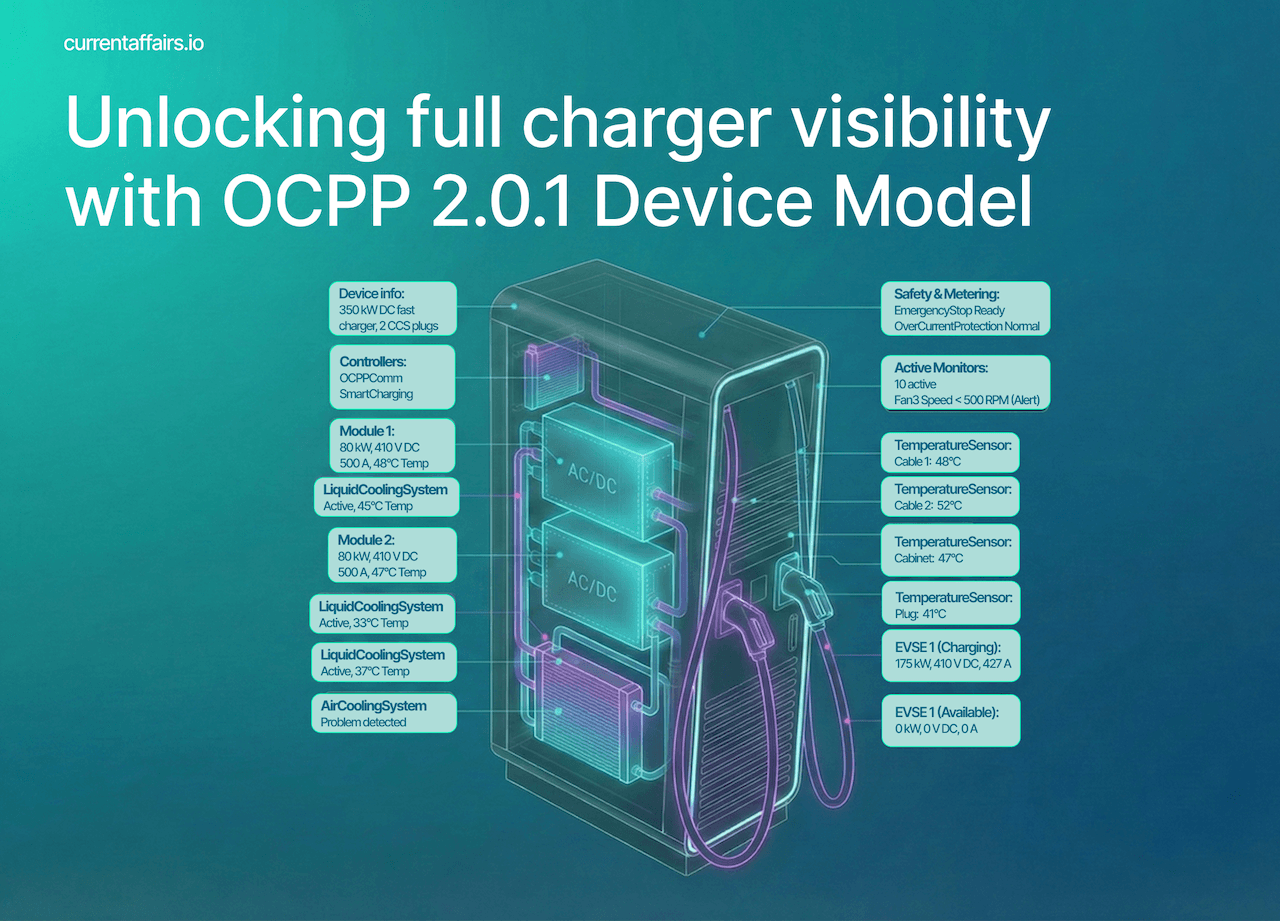
Imagine you need to represent a 350kW High Power Charger (HPC) with dual power modules, multiple temperature sensors, liquid and air cooling systems, and a full suite of configured monitors.
With everything you’ve learned about the Device Model’s capabilities, how would you structure this in your CSMS and present it to your operations team?
Lacking the design chops to mock this up myself (my Figma skills peaked at drawing rectangles and lines), I turned to Claude with that exact challenge. Here’s what my friend Opus 4.5 produced – feel free to steal liberally or judge harshly. ;)

You can download the Full Inventory report for this example charger below. Substack doesn’t allow uploading JSON or ZIP files. However, CBZ files work, which are literally just ZIP archives. So go ahead and download the file, rename the file ending to “.zip”, and unzip it to see the JSON content.
Best practices for adoption
Based on implementation experience across the industry, several patterns emerge for successful Device Model deployment:
Start with Full Inventory reports when onboarding any station, but verify against your asset management system. In an ideal world, you'd build your internal representation entirely from what the station reports. In reality, many manufacturers implement the Device Model minimally, so the report may be incomplete. Use the Full Inventory as a baseline, flag gaps where the station reports less than your asset records indicate, and treat those gaps as integration debt to address with the vendor.
Use Configuration Inventory reports for audit and drift detection. Periodically request these reports from your charger infrastructure and compare against your expectations. Discrepancies indicate either unauthorised local changes or sync issues.
Implement monitoring progressively. Begin with critical thresholds (temperature, error states) and expand based on operational learnings. The stations will tell you what they can monitor – listen to them.
Build UI that adapts. When the Device Model reports that a variable is an OptionList with specific valid values, generate a dropdown. When it’s a number with minLimit and maxLimit, generate a bounded slider or input. Your interface becomes self-documenting.
Plan for the hierarchy. Station-level components behave differently from EVSE-level components. A power limit on the station affects all EVSEs. A power limit on an EVSE affects only that charging point. Your management logic needs to understand this inheritance.
The gap between specification and reality
The Device Model described in this article represents what OCPP 2.0.1 makes possible, not necessarily what you’ll encounter in the field today. Many charging station manufacturers implement the Device Model minimally, exposing only mandatory components and variables while keeping richer telemetry behind proprietary interfaces. The reasons range from legitimate (implementation complexity, verbosity of the Device Model, and resource-constrained hardware) to strategic (maintaining differentiation and vendor leverage).
This gap matters. The Device Model’s value scales with adoption depth. A network where every station fully self-describes, exposes configurable monitoring, and reports component-level status is fundamentally easier to operate than one where you’re stitching together partial OCPP data with manufacturer-specific APIs and manual asset records.
For CPOs, the path forward is twofold: demand comprehensive Device Model implementation in procurement, and design your CSMS to leverage it fully when it’s available while gracefully handling gaps when it isn’t. The stations that report more will cost less to operate. Make that a selection criterion.
If you want to know which charger manufacturers and CSMS providers have already been certified by the Open Charge Alliance (OCA) for properly implementing the Device Model, then head over to the OCA’s certification page and filter the protocol version for OCPP 2.0.1 and the certificate type for “D: Advanced Device Management”. You’ll only see a handful of companies as a result.
The Device Model is, in my opinion, the most powerful and important feature of OCPP 2.0.1. If you have a bit of time and want to learn more about all the wonderful new goodies this version brings to the table – such as better transaction handling, stronger cybersecurity, native ISO 15118 support – then I highly recommend watching the Open Charge Alliance (OCA)’s OCPP 2.0.1 tutorial webinar:
Hopefully this analysis has been useful – maybe even a catalyst for rethinking your approach. If you’re a charging station vendor, the Device Model isn’t just a compliance checkbox; it’s a competitive differentiator. The manufacturers who expose rich, queryable infrastructure that can be easily monitored will win the CPOs who are serious about scaling. If you’re a CPO, this is your leverage: demand implementation depth, not just certification logos, and make it a weighted criterion in every tender.
Yes, the Device Model comes with a learning curve and upfront investment. But the payoff is real: vendors who implement it fully will close deals with sophisticated operators; CPOs who require it will build networks that scale without scaling their headcount. That’s not a theoretical benefit – it’s the difference between infrastructure you manage and infrastructure that manages you.
In my next article (Part 2), we’ll examine why full adoption has been slow, including the role of MQTT as a parallel telemetry channel, the “Shadow OCPP” phenomenon where manufacturers maintain proprietary backchannels alongside your CSMS, and what it will take for the industry to realise the Device Model’s full potential.
Great article, Mark. I could not have described the OCPP device model any better.
-Franc
Exceptional article. Thanks for this lesson.
"This replaces the generic StatusNotification and the sometimes cryptic vendorErrorCodes from OCPP 1.6 with precise, actionable information." — I would say this is not as good as suggested.
Indeed, with OCPP 2.0.1, you now know which specific component is faulted (has a problem), which is a step forward. However, a single component can still have many different types of problems.
In practice, the StatusNotification.vendorErrorCode from OCPP 1.6 has simply moved to NotifyEventRequest.eventData.techCode in OCPP 2.0.1. Consequently, the actual content remains the same: vendor-specific error codes.