
How OCPP 2.1 and ISO 15118-20 enable V2G grid code implementations
Grid codes define what a V2G unit must do. OCPP 2.1 and ISO 15118-20 are how those rules actually travel, from a grid operator’s control room to the inverter inside your car.

When an EV feeds power back to the grid, it stops being a consumer and becomes a generator. And generators, as explored in the previous article, don’t get to play by their own rules. The grid operator says: when frequency drops, ramp up discharge. When voltage rises, absorb reactive power. When the grid is in emergency, trip off. These are not suggestions, they are the grid code obligations that come with being a power-producing device.
But a rule written in a regulation is only the theory. To put the theory into practice, we need a way of reaching the power electronics inside an electric vehicle. Something has to carry each instruction from the grid operator’s systems into the on-board charger inside the car. That carrier is a chain of communication protocols, each layer passing the baton to the next. Understanding that chain is what this article is about.
The protocol names may be unfamiliar to some readers. The goal is not to leave you quoting message parameters, but to understand what each layer is responsible for, how they connect to one another, and where the chain is still being built.
In this article, you will learn:
How grid code parameters travel from a grid operator all the way to your EV’s on-board inverter, via a three-layer protocol stack
What OCPP 2.1’s two V2G sections do: Section Q (how bidirectional power is orchestrated) and Section R (how grid compliance parameters are delivered), and how they relate to each other
What ISO 15118-20 offers for bidirectional charging: DC and AC power transfer services, message flows, and the difference between scheduled and dynamic control
Why bidirectional power control alone is not sufficient for grid code compliance, and what ISO 15118-20 Amendment 1 adds to close that gap
How the European and US approaches diverge, and what IEC 61851, IEEE 1547, and SAE J3072 each represent
Where the certification landscape stands in 2026
What you are about to read is a summary of material spread across hundreds of pages in the OCPP 2.1 and ISO 15118-20 standards. I’ve done my best to be as accurate as possible while making it digestible. Given the complexity of the subject, this article runs longer than most, but I’ll guide you through it step by step.
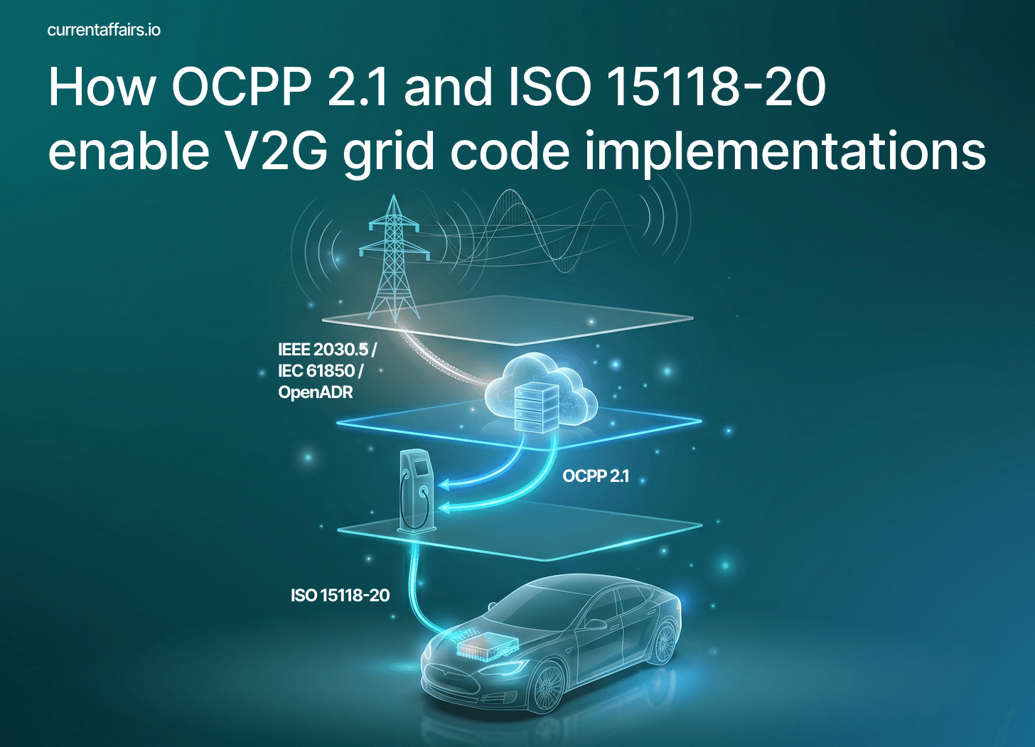
The three-layer chain
Grid code parameters need to travel from a utility control room to the inverter inside an EV. They do this in three hops, each handled by a different protocol:
Grid Operator
     ↓  IEC 61850 / IEEE 2030.5 / OpenADR
CSMS (Charging Station Management System)
     ↓  OCPP 2.1  (Sections Q and R)
Charging Station
     ↓  ISO 15118-20  (base standard + Amendment 1)
EV On-board Inverter
A quick note: I use CSMS (Charging Station Management System) here rather than CPMS as in previous articles. They mean the same thing. CSMS is the term OCPP uses, so I’ve followed the standard’s lead here.
The first hop — from grid operator to CSMS — uses utility-to-aggregator protocols. In Europe these are typically IEC 61850 or OpenADR; in North America, IEEE 2030.5 and OpenADR are widely used. This article will not go deep on those; the more important story is what happens in the next two hops.
The CSMS — the cloud backend that manages a fleet of charging stations — is the translator and aggregator. It receives grid signals from the operator (or an intermediary V2G aggregator that sits between a CSMS and the grid operator), interprets them, and pushes them to individual chargers. The OCPP 2.1 protocol, which has become an official IEC standard (IEC 63584-210) in 2025, handles both legs of this: Section Q defines how bidirectional power flow is controlled, and Section R defines how grid compliance parameters are delivered. From the charging station to the EV, ISO 15118-20 carries the baton — including a new addition, Amendment 1, that enables the last and hardest mile of all.
OCPP 2.1 Section Q: eight ways to orchestrate bidirectional power
OCPP is the language charging stations and their backend management systems use to communicate. Version 2.0.1, now being deployed across the globe, handles session management, authentication, metering, and smart charging, among other use cases. OCPP 2.1 extends this with bidirectional power transfer as a native, first-class capability, and is backwards-compatible to OCPP 2.0.1.
The central contribution of Section Q is a set of eight operation modes that define how the CSMS controls power flow at a bidirectional charging station:
ChargingOnly: Default; no bidirectional operation. Also used as fallback when no mode is explicitly set.
ExternalSetpoint: An external Energy Management System (EMS) controls the power target; the CSMS grants permission.
ExternalLimits: An EMS controls power ceilings for charge and discharge, rather than a specific target.
CentralSetpoint: The CSMS provides a specific power target, updated in real time.
CentralFrequency: Similar to LocalFrequency, but frequency is measured centrally. A single calibrated meter feeds the CSMS, which continuously pushes updated setpoints to stations as frequency changes. Used where the cost of a precision meter in every charger is prohibitive. Falls back automatically to LocalFrequency if the CSMS stops sending updates.
LocalFrequency: The charging station reads local grid frequency and responds autonomously using a pre-configured frequency-power curve. No CSMS instruction required per event.
LocalLoadBalancing: The charging station monitors the building’s upstream power meter and adjusts output to stay within defined thresholds.
Idle: The EV is connected but neither charging nor discharging. Used for preconditioning or standby.
For grid stability services, the two most relevant modes are CentralFrequency and LocalFrequency. The table above describes both; the key distinction is that LocalFrequency relies on nobody at all. The charging station reads frequency directly at the socket, compares it to a curve configured in advance, and adjusts its output immediately. No message, no round-trip, no delay.
This matters because frequency events happen fast. When a large power plant trips offline, grid frequency can drop within seconds. The industry uses two distinct tiers of frequency response to manage this:
FCR: Frequency Containment Reserve (also called primary frequency response) is the first line of defence. It must activate within seconds, automatically, without any external command. In LocalFrequency mode, the charging station holds a frequency-power lookup table — the same droop curve described in the previous article — and adjusts its output continuously as frequency deviates. When frequency falls, the station discharges more. When it rises, it charges more. The response is proportional and instantaneous, requiring no involvement from the CSMS.
aFRR: automatic Frequency Restoration Reserve (secondary frequency response) is the second tier. It begins gradually replacing FCR from around 30 seconds after a frequency event and must reach full contracted capacity within 15 minutes. Unlike FCR’s autonomous response, aFRR is coordinated: the CSMS sends an activation signal to the charging station, which then adds a power delta on top of its configured baseline. The spec also specifies a minimum ramp rate of around 20% of offered power per minute.
Section Q also extends the existing OCPP charging schedule mechanism with three new power-control fields:
setpoint(signed, ±): the power target the EV should follow as closely as possible. Positive means charging; negative means discharging.limit(+): a ceiling on charging power. The EV must not exceed it.dischargeLimit(−): a ceiling on discharge power. The EV must not exceed it in the discharge direction.
The setpoint/limit distinction matters in practice. A setpoint is a target, i.e. the EV is expected to hit it. A limit is a boundary: the EV must not cross it, but has freedom to operate anywhere below. The CSMS uses setpoints for grid service delivery (where hitting a specific value matters) and limits for constraint management (where staying below a threshold is all that matters).
OCPP 2.1 Section R: delivering grid compliance parameters to the charger
Section Q handles power flow orchestration: the dispatch and scheduling layer. Section R handles something entirely different: delivering the technical grid code parameters that determine how a bidirectional asset behaves under grid stress.
These two sections are not alternatives. Section Q says “discharge at 8 kW between 5 pm and 7 pm.” Section R says “if voltage rises above 110% of nominal, trip within two seconds” and “if frequency drops below 49.8 Hz, increase discharge with a 2% droop.” One governs commercial dispatch; the other governs grid safety behaviour. Both are needed.
The central OCPP message in Section R is SetDERControlRequest. DER (Distributed Energy Resource) is the utility industry’s label for any small-scale generation or storage asset connected to the distribution grid. This message allows the CSMS to push grid code parameters directly to a charging station, where they are stored persistently, meaning they must survive a reboot or a power cycle.
The range of parameters it can carry maps directly to the grid code requirements covered in the previous two articles:
FreqDroop: The autonomous frequency-power response curve — the LFSM/FCR mechanism in OCPP terms. Configures three things: the dead band (the frequency range around 50 Hz where no response is required), the droop factor (how much power changes per Hz of deviation — typically 2% for V2G), and the response time. Once set, the station responds to frequency events without any CSMS involvement.
VoltVar: The Q(U) reactive power curve covered in the previous article. Defines how the inverter adjusts reactive power as local voltage rises or falls — injecting reactive power when voltage dips, absorbing it when voltage climbs. Configures the voltage breakpoints, the reactive power levels at each point, and a dead band around nominal voltage where no action is taken.
VoltWatt: Active power as a function of local voltage. When voltage rises too high — typically because of excess solar generation on the local network — the inverter automatically reduces its active power output rather than continuing to push energy into an already-overvoltage network. Less commonly used than
VoltVar, but important in high-PV neighbourhoods.HVMustTrip / LVMustTrip: The hard voltage trip thresholds for interface protection. If voltage exceeds the high-voltage (HV) limit or falls below the low-voltage (LV) limit and stays there beyond the defined hold time, the unit must disconnect from the grid. These are the UV1/OV1 thresholds (80% and 110% of nominal voltage, 2-second trip time) from the previous article, delivered here as configurable OCPP parameters.
HFMustTrip / LFMustTrip: The hard frequency trip thresholds — equivalent to the voltage trips but for the frequency dimension. If frequency rises above the high limit or falls below the low limit beyond the defined hold time, the unit must disconnect. Under EN 50549-1 these are set at 47.5 Hz and 51.5 Hz; the exact values and timing are configured here per site.
EnterService: Reconnection rules after a trip event. When a V2G unit disconnects because voltage or frequency went out of bounds, it cannot simply reconnect the moment conditions return to normal, since a mass simultaneous reconnection by thousands of devices would cause a fresh grid disturbance.
EnterServicedefines the voltage and frequency window within which reconnection is permitted, a mandatory intentional delay before attempting it, and the ramp rate at which power must be restored gradually. It is the orderly queue that prevents the cure from becoming a second crisis.LimitMaxDischarge: A configurable ceiling on discharge power, expressed as a percentage of the station’s rated capacity. Used by grid operators to cap how much power a V2G asset — or a whole fleet of them — can export into a constrained network segment, without needing to stop the session entirely.
Getting confused with all the acronyms? Don’t worry, I got you covered with the Acronym Survival Guide.
Controls come in two varieties. Default controls have no expiry, they are always active and define the station’s permanent grid behaviour at a given site. Scheduled controls have a defined start time and duration; they activate at the specified moment, supersede any lower-priority default of the same type, and are automatically removed when their duration expires. This lets a grid operator push a temporary configuration change — tightening discharge limits during a congestion event, for instance — without permanently altering the site’s baseline settings.
Here is where the architecture forks depending on whether the deployment is DC or AC V2G.
For DC V2G, the inverter is inside the charging station. The station receives SetDERControlRequest, stores the parameters, and its own power electronics execute them directly. The EV’s role is to provide battery capacity; grid compliance responsibility sits entirely with the EVSE (Electric Vehicle Supply Equipment, i.e. the charging station’s device that controls the power flow). ISO 15118-20 tells the charger what power the EV can deliver, but the charger’s inverter is the regulated grid asset.
For AC V2G, the inverter is inside the EV. The charging station is, in grid compliance terms, a smart connection point. When the CSMS pushes DER parameters via SetDERControlRequest, the charger receives them. Active power limits — such as a maximum discharge ceiling — can be enforced by the charging station directly, by capping the target value it sends in each ChargeLoopRes (’Res’ = response) during the session. Inverter configuration parameters — frequency droop curves, Q(U) reactive power curves, trip thresholds — are different: those must be loaded into the EV’s own inverter, which is only possible via ISO 15118-20 Amendment 1’s AC DER services (AC_DER_IEC for Europe, AC_DER_SAE for North America). We’ll cover those in a second.
Section R also closes the reporting loop. When a grid event triggers a DER control — say, an over-voltage event activates the VoltWatt curve and the station reduces its discharge power — it sends a NotifyDERAlarmRequest to the CSMS, identifying which control was triggered and what grid fault caused it. When the event clears, it sends the alarm-ended notification. The CSMS has a live picture not just of what it instructed, but of what actually happened.
 and Section R (DER parameters) of OCPP 2.1 reach the charging station, and fork for DC vs AC V2G")
ISO 15118-20: the charger-to-EV conversation — BPT services
ISO 15118 is the standard that governs communication between an EV and a charging station over the charging cable. ISO 15118-2 — covering unidirectional AC and DC charging and Plug & Charge — became mandatory at newly installed EU public chargers in January 2026. ISO 15118-20 is the successor standard, adding bidirectional power transfer as a native capability.
As you can see, OCPP 2.1 and ISO 15118-20 both treat bidirectional power flow as first-class citizens and are essential to unlock V2X (Vehicle-to-Home and Vehicle-to-Grid) use cases.
For bidirectional charging, ISO 15118-20 defines two BPT (Bidirectional Power Transfer) services: AC_BPT and DC_BPT. The architectural difference mirrors the previous article’s AC/DC split.
In DC_BPT, the inverter is in the charging station. The EV connects via a DC link (e.g. a CCS plug), providing battery capacity. The EV declares its charge and discharge capabilities; the charger manages the DC-to-AC conversion. The EV and charger negotiate power envelopes at the start of the session and exchange updated limits during the (dis-)charging message cycle loop.
In AC_BPT, the inverter is in the EV’s on-board charger (OBC). The charging station is essentially a metered connection point. The EV must handle the AC-to-DC conversion in both directions, and its inverter is the grid-facing device.
Session setup
Both services follow the same session flow. Before power starts flowing, there is a four-step negotiation phase:
Service Discovery: the EV asks the charging station what services it offers. The charging station responds with its list of supported ServiceIDs. For a BPT-capable site, this list includes AC_BPT (ServiceID 5) or DC_BPT (ServiceID 6). For a site using Amendment 1, it will also include AC_DER_IEC (ServiceID 10) or AC_DER_SAE (ServiceID 11).
Service Detail: the EV requests the parameter set for each service it is interested in. The charging station responds with the service parameter list for that service. This is where operationally important choices are surfaced: the control mode (Scheduled or Dynamic, see below), the connector type, and — for the AC DER services — the DER capability requirements or supported functions. Selecting Dynamic control mode here is what enables real-time setpoint following during charging.
Service Selection: the EV confirms its chosen service and parameter set. From this point, both sides know exactly what the session will look like.
Charge Parameter Discovery: EVCC and SECC exchange their physical capabilities and limits for the chosen energy transfer service. In a BPT session, the EV declares its discharge capabilities — maximum and minimum discharge power, current limits — and the charger responds with its own discharge limits. For the AC DER services, this is also where the detailed DER configuration is delivered: droop curve parameters, voltage and frequency trip thresholds, Q(U) reactive power curve breakpoints, and enter-service settings. This mutual handshake establishes what the session will look like before a single watt moves.

Control modes and the ChargeLoop
After this exchange, the session enters one of two control modes.
Scheduled mode follows a pre-agreed power schedule, which is a time-indexed list of setpoints agreed at session start and applied throughout. This works well for predictable use cases: overnight energy arbitrage, for example, where the EV discharges during the evening peak and charges cheaply at night according to a schedule the CSMS prepared in advance.
Dynamic mode allows setpoints to be updated throughout the session without interrupting it. With every ChargeLoop message (continuously exchanged during power flow), the charger can send the EV a new power target. This is the mode required for genuine real-time grid services — frequency response, congestion management, direct grid operator setpoints — where the optimal power level may change every few seconds.
The ChargeLoop is the operational heartbeat of the session. Each cycle, the EV sends its current limits and status; the charger responds with updated targets. ISO 15118-20 governs both sides of each exchange: the charger must respond within 0.5 seconds of receiving the EV’s request (the message timeout), and the EV must send its next request within 0.5 seconds of receiving the response (the sequence timer). Taken together, these two constraints bound each full ChargeLoop cycle to under one second. This is a protocol guarantee, not just typical behaviour. For frequency response applications, where the relevant timescale is seconds, that guaranteed cycle rate sits right at the practical boundary of what is achievable over a software-based connection.
At this point, however, we reach the limit of what BPT services alone can do. DC_BPT and AC_BPT are power flow protocols. They can instruct an EV to “charge at 7 kW” or “discharge at 7 kW.” They can agree on power envelopes and exchange state-of-charge information. What they cannot do is say “configure your inverter with this frequency droop curve” or “enable Q(U) voltage support with these specific voltage breakpoints.” That is the domain of DER control. And for AC V2G, it requires a separate protocol extension. That extension is Amendment 1.
ISO 15118-20 Amendment 1: the DER layer reaches the car
Amendment 1 — currently in draft form, expected to be finalised in the second half of 2026 — adds two new AC DER services to ISO 15118-20. These are not replacements for AC_BPT; they are extensions of it that add the grid code compliance layer on top of bidirectional power control.
The two new services reflect a fundamental divergence in grid code standards between Europe and the United States:
AC_DER_IEC is built on IEC 61851-1 Edition 4: the foundational IEC standard for EV conductive charging systems, the latest edition of which introduced specific DER behaviour requirements for bidirectional AC charging. This is the European path, aligned with EN 50549-1 across the EU and VDE 4105 for Germany, in particular.
AC_DER_SAE is built on IEEE 1547-2018 and SAE J3072: the US standards for grid interconnection of distributed energy resources and V2G communication specifically. This is the path for North American deployments, aligned with state interconnection rules, California Rule 21, and UL 1741 certification.
The two services accomplish the same goal — configuring an EV inverter for grid code compliance — but they differ fundamentally in who declares what.
AC_DER_IEC is site-driven. During ServiceDetail — the second step of the pre-session negotiation, as discussed above — the charging station sends the EV a requirements bitmap (12 flags, one per DER function) declaring which grid compliance functions are required at this location. For instance, “you must support frequency-watt response, Q(U) reactive power support, and fault ride-through.” The EV can only select this service if it supports all the required functions. The site sets the bar; the EV qualifies or doesn’t.
AC_DER_SAE is EV-driven. The capability declaration comes later than in the IEC path: during ChargeParameterDiscovery — the fourth step — the EV sends a capabilities bitmap (SupportedModes, 27 flags) declaring which IEEE 1547 functions it supports. The charger responds in the same handshake with an EnabledModes bitmap confirming the subset it wants active for this session. The EV declares what it can do; the site configures accordingly.
The difference in bitmap size reflects the underlying standards. IEC 61851-1 Edition 4 defines a compact European DER function set; IEEE 1547-2018 is more granular: it treats may-trip, must-trip, and momentary cessation as distinct trip categories for both over- and under-voltage, and adds functions such as enter-service authorisation and constant setpoint modes that have no direct IEC equivalent. Both services then use ChargeParameterDiscovery to deliver the full DER configuration to the EV’s inverter.
In AC_DER_SAE, this means a complete set of IEEE 1547 trip curves: six voltage trip curves (overvoltage and undervoltage, in must-trip, momentary cessation, and may-trip variants) and four frequency trip curves (over and under, must-trip and may-trip). It means frequency droop settings. And it means an enter-service authorisation — a boolean flag that grants the EV explicit permission to discharge at this specific site. Not every site allows export, and this flag is the formal, protocol-level mechanism by which the site grants or withholds that permission.
In AC_DER_IEC, the equivalent block delivers fault ride-through parameters, reactive power support curves (Q(U), Q(P)), and active power response curves (frequency-watt, volt-watt) — all determined by the requirements bitmap the site set in ServiceDetail.
Once the session is active, both services extend the ChargeLoop heartbeat with DER reporting. With every cycle, the EV reports back: its operational state, its connection status relative to the grid, and a bitmap of any active alarm conditions — overvoltage, undervoltage, over-frequency, under-frequency, and several others. The charging station — and via OCPP 2.1 Section R, the CSMS — has a continuous live view of what each connected EV inverter is seeing and doing.
In AC_DER_IEC, the charger can additionally pass real-time DSO setpoints with every ChargeLoop cycle: a reactive power setpoint or a power factor setpoint, updated continuously as grid conditions evolve.
The two paths: static configuration and dynamic setpoints
This is what genuinely dynamic, remotely managed grid code compliance looks like — but it operates on two distinct timescales, through two distinct paths.
The static configuration path handles droop curves, trip thresholds, Q(U) curve shapes, and enter-service settings. These are pre-loaded onto the charging station by the CSMS via OCPP 2.1 Section R. When an EV connects and the session reaches ChargeParameterDiscovery, the charging station delivers this configuration to the EV’s inverter in full. From that point, the EV acts autonomously — no further signal from the grid operator is required for FCR droop response or fault ride-through.
The dynamic setpoint path handles real-time power targets and reactive power setpoints. In CentralFrequency or CentralSetpoint mode, the CSMS continuously pushes updated values to the charging station via OCPP 2.1 Section Q. The charging station embeds the current setpoint into each ChargeLoop response to the EV. This is the path used for aFRR activation and for DSO-dispatched reactive power instructions in AC_DER_IEC sessions.

A word of caution, though, on what “every cycle” means in practice. The 0.5-second figure is the heartbeat rate of the EV-to-charger conversation, not the latency of the full chain. A setpoint change originating at a grid operator must travel through IEC 61850 (or IEEE 2030.5, for example) to the CSMS, be translated into OCPP, travel over a WebSocket connection to the charging station, and then appear in the next ChargeLoop response to the EV. That full round-trip is measured in seconds, not milliseconds — and on a congested network it may be longer still. This is precisely why LocalFrequency mode in OCPP 2.1 exists, and why the autonomous frequency droop pre-configured via Section R is the practical mechanism for FCR: fast-response grid services cannot rely on a central command reaching the device in time. The 0.5-second cycle mentioned above for the ChargeLoop messages serves a different purpose: it keeps the EV and charger in tight synchronisation during an active session, so that when a locally-detected grid event triggers an autonomous response, the charger knows exactly what the EV’s inverter is doing.
The certification fork
The AC_DER services bring different certification requirements depending on which side of the Atlantic you are on.
In the United States:
For DC V2G, the EVSE inverter is certified against UL 1741 SB (Supplement B), which implements IEEE 1547-2018 requirements for inverter-based DERs. This path is well-established and commercially available.
For AC V2G, the vehicle’s on-board inverter is certified against SAE J3072 (the EV-specific IEEE 1547 compliance standard), and the EVSE against UL 1741 SC (Supplement C), finalisation expected in 2026. Stellantis demonstrated a complete SAE J3072-compliant AC V2G stack at the Detroit V2G Forum in October 2025, with NREL (the US National Renewable Energy Laboratory, a federal research lab under the Department of Energy) confirming IEEE 1547 ride-through compliance. This is the first public end-to-end US demonstration of the full stack.
In Europe:
For either DC or AC V2G, the system is certified against EN 50549-1 using a test report based on EN 50549-10 (or VDE 0124-100 for Germany). Under VDE 4105, notably, certification is system-level: a specific vehicle model, charging cable, and wallbox must be certified together as an integrated unit.
ISO 15118-20 conformance can, hopefully from 2026, be verified through ISO 15118-21 (common requirements), ISO 15118-22 (AC requirements), and ISO 15118-23 (DC requirements), the dedicated conformance testing standards.
The complete picture
Let me trace the full chain through a single concrete example. A German grid operator detects rising voltage in a residential network zone on a sunny July afternoon — rooftop solar is flooding the local grid. It needs the V2G fleet in that zone to absorb reactive power to bring voltage back down.
1. Grid operator → CSMS. The operator signals updated Q(U) reactive power requirements to the aggregator’s CSMS via IEC 61850. The CSMS translates this into OCPP.
2. CSMS → Charging Station (Section R). The CSMS sends a SetDERControlRequest carrying a VoltVar control with an updated Q(U) curve — specifying how much reactive power each station should inject or absorb at each voltage level. For DC V2G stations, this is executed directly by the EVSE inverter, immediately and autonomously.
3. CSMS → Charging Station (Section Q). Simultaneously, the CSMS sends a ChargingProfile with operationMode = CentralSetpoint, directing each station’s active power schedule for the afternoon. Commercial dispatch and grid compliance parameters travel through separate mechanisms but arrive at the same device.
4. Charging Station → EV (ISO 15118-20 Amendment 1, AC V2G). For AC V2G sessions, the VoltVar configuration — the Q(U) curve breakpoints and the reactive power levels at each voltage step — is delivered to the EV’s on-board charger during the ChargeParameterDiscovery phase, before power flows. Once loaded, the EV inverter applies the Q(U) profile autonomously in response to voltage it measures locally. Mid-session, the CSMS can push a real-time reactive power setpoint (a single scalar value) to the EV via the ChargeLoop response in Dynamic mode; this is not a curve change but a DSO dispatch instruction on top of the configured curve. Changing the Q(U) curve shape mid-session would require a service renegotiation.
5. EV → Charging Station → CSMS (reporting path). During every ChargeLoop cycle, the EV reports its DER operational state and any active grid events. Significant events — an over-voltage alarm, a frequency trip — are forwarded by the charging station to the CSMS via NotifyDERAlarmRequest. The operator has visibility of what each asset is doing.
This is what a fully instrumented, dynamically configurable V2G grid asset looks like. And it requires every link in this chain to function.
To tie it all together visually, here is the complete message flow — from grid operator signal to EV inverter response — as a sequence diagram.

Where things stand in 2026: OCPP 2.1 has been published; Sections Q and R are available for implementation. ISO 15118-20 is published and being deployed, though some commercial programmes today — including Ford/Octopus — are still running on ISO 15118-2 with proprietary extensions. Amendment 1 is in draft form, expected to finalise in H2 2026. The EU’s AFIR regulation mandates ISO 15118-20 compliance for bidirectional charging communication by 1 January 2027 — a tight window for charger manufacturers to have Amendment 1-capable hardware in production.
The commercial V2G market is running slightly ahead of its standardised communication layer, and that is not a problem in itself — pilots and bespoke arrangements are how the industry builds experience. What the completion of this chain unlocks is different: Section Q and Section R form the CSMS layer, ISO 15118-20 base is the power control layer, and Amendment 1 is the last mile from charger to inverter. The pieces are in place. The chain is not yet complete everywhere — but the direction is clear.
Excellent explanation of a complex subject. In my role as technical editor for the Open Charge Alliance I am currently writing a paper on how to map the OCPP 2.1 DER control functions onto the ISO 15118-20 Amd. 1 functions. OCPP 2.1 was released in January 2025 when ISO was in the process of defining the Amendment 1. At that time the content of the OCPP DER control had been coordinated with the ISO working group. During 2025, however, the Amendment was overhauled, because IEC and SAE could not agree on a joint approach. The AC_DER service was changed into two completely different services AC_DER_IEC and AC_DER_SAE. As a consequence the mapping from OCPP to ISO is not as straightforward anymore as it used to be. The mapping to AC_DER_SAE is still okay (because OCPP 2.1 DER was inspired by IEEE 2030.5, which is prescribed by SAE J3072), but the mapping to AC_DER_IEC needs some conversions (e.g. some DER curves need to be represented as a droop in AC_DER_IEC). The ISO 15118-20 Amd. 1 is not yet final, so we may hold the publication of this paper until the official publication of the amendment.
This is one of the technically deeper articles that I read lately in the space, yet explained in simple words. Thanks @Marc Mültin . Keep sharing.