
How EVs, chargers and the CPMS talk: a tech deep dive into smart charging
Understanding the protocol handshake that enables dynamic load management, price signals, and grid integration

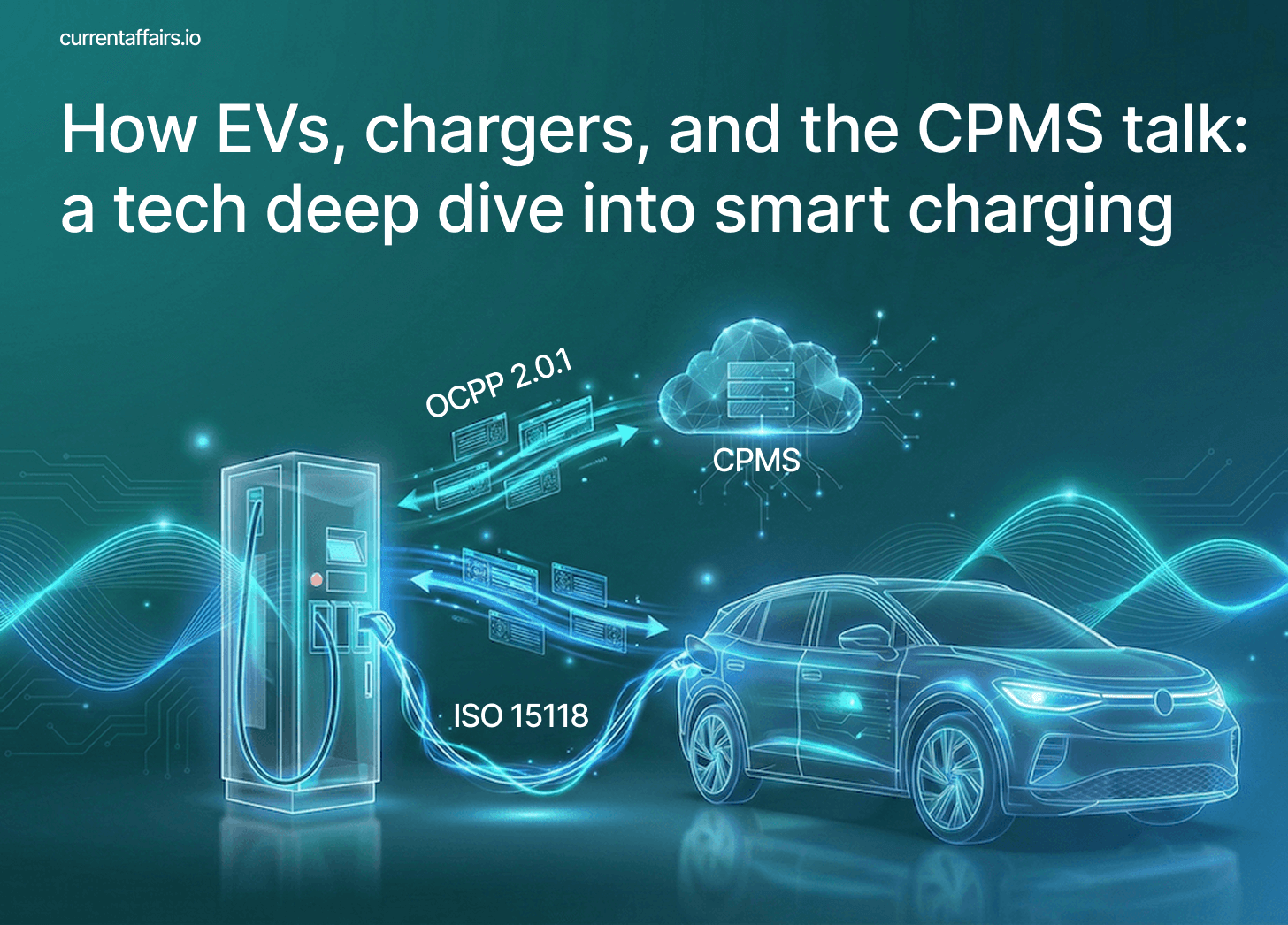
You plug in your EV, tap your card or app (or not if both “speak” Plug & Charge), and power flows. Simple, right? Well, behind that simple act is a surprisingly sophisticated three-way conversation happening between your car, the charger, and a backend system somewhere in the cloud.
In this article, I’ll walk you through exactly how smart charging works when ISO 15118-2 (EV-to-charger communication) meets OCPP 2.0.1 (charger-to-backend communication). By the end, you’ll understand:
The complete message flow from when an EV states its charging needs (
ChargeParameterDiscoveryReq) through to the backend’s response (SetChargingProfileRequest) and back to the vehicleWhat data the EV actually shares — and critically, what it doesn’t (spoiler: SOC is mandatory, but energy capacity and need are optional, which can create a real problem for CPOs)
How charging schedules are built — the layered profile system, composite schedules, and the “minimum of all limits” rule that guarantees safety
Mid-session renegotiation — what happens when grid conditions change or the driver updates their departure time
Why this matters commercially — from fleet depot optimisation to future V2G revenue streams
I’ll use a VW ID.4 as our example vehicle throughout, with actual message structures and realistic parameters. Whether you’re a CPO trying to implement smart charging, an EV or charger manufacturer working on protocol compliance, or just a curious techie wanting to understand the mechanics, this should give you a solid foundation.
The cast of characters
Before we dive in, let’s meet our three protagonists:
The Electric Vehicle (EV) knows how much energy it needs, when you want to leave (provided that you input this information in the car OEM’s in-car or mobile app), and what its battery can handle. It communicates this through ISO 15118 — a protocol that runs over the charging cable itself (yes, the cable carries both power and data).
The Charging Station is the intermediary. It speaks ISO 15118 to the car and OCPP to the cloud. ISO 15118 actually refers to that specific communication component inside the charger as the SECC (Supply Equipment Communication Controller).
The Charge Point Management System (CPMS) is the brains of the operation. It sits in the cloud, monitors the entire network, and decides how much power each charger can deliver based on power available at the site, grid constraints, energy prices, or whatever other factors the operator cares about.
Act one: the EV states its case
When your EV plugs in and high-level communication (via ISO 15118) kicks off, the first substantive exchange is the ChargeParameterDiscovery. This is where your car essentially says: “Here’s what I need, what I can handle, and when I’d like to be done.”
In ISO 15118-2, the EV sends a ChargeParameterDiscoveryReq message containing its charging parameters. For DC charging, this looks something like:
ChargeParameterDiscoveryReq (ISO 15118-2)
EV → Charging Station
├─ RequestedEnergyTransferMode: DC                        [MANDATORY]
├─ MaxEntriesSAScheduleTuple: 12                          [optional]
└─ DC_EVChargeParameter:
    ├─ DC_EVStatus:                                       [MANDATORY]
    │   ├─ EVReady: true                                  [MANDATORY]
    │   ├─ EVErrorCode: NO_ERROR                          [MANDATORY]
    │   └─ EVRESSSOC: 20%                                 [MANDATORY]
    ├─ EVMaximumCurrentLimit: 350 A                       [MANDATORY]
    ├─ EVMaximumVoltageLimit: 408 V                       [MANDATORY]
    ├─ EVMaximumPowerLimit: 135000 W                      [optional]
    ├─ EVEnergyCapacity: 77000 Wh                         [optional]
    ├─ EVEnergyRequest: 54000 Wh                          [optional]
    ├─ DepartureTime: 7200 (seconds from now)             [optional]
    ├─ FullSOC: 100%                                      [optional]
    └─ BulkSOC: 80% (when to start reducing power)        [optional]
Let’s unpack these values and use the example of a mid-size EV, the ID.4. It has a 400 V-class battery architecture with a nominal voltage around 352V (96 cells in series at 3.67 V nominal).
The EVMaximumVoltageLimit of 408 V represents the upper voltage when nearly full. The EVMaximumCurrentLimit of 350 A combined with voltage gives us roughly 125-135 kW peak charging power (P = V x A) .
Educate your EV drivers on available charging power — they’ll thank you
There’s a lack of communication and education about the maximum power available at a charger and the maximum power the vehicle’s battery can be charged with. In my last article on A clear guide to load management, phase rotation, and smart charging, I explained that the actual delivered power will be the minimum of the charger’s capability, the cable capacity, and the vehicle’s acceptance rate.
If you’re charging at a 350 kW charger but the maximum charging power doesn’t climb beyond the 135 kW mark, then maybe it’s not the charger or CPO (Charge Point Operator) at fault — maybe it’s just your EV not being able to take more power in.
The CPO who clearly communicates (and explains) the real available charging speed via the charger’s display, app, and roaming partners will be rewarded with the trust and high CSAT rating of their EV drivers. Keep that in mind.
Alright, sorry for that slight detour, let’s get back to the elements of the ChargeParameterDiscovery message.
Notice something frustrating here? EVRESSSOC1 (the current state of charge) is mandatory, but EVEnergyCapacity and EVEnergyRequest are optional. This can create a real problem for smart charging decisions.
If you’re a CPO trying to calculate how much energy a vehicle needs, the ideal information is the energy amount directly — either through EVEnergyRequest (the energy the EV needs for a full charge) or by calculating it from EVEnergyCapacity (the size of the vehicle’s battery in kWh, e.g. 77 kWh for an ID.4) and EVRESSSOC. But if an EV implementation only sends the mandatory EVRESSSOC of 20% without the battery capacity, you’re stuck. Is that 20% of a 45 kWh battery (needing ~36 kWh) or a 77 kWh battery (needing ~62 kWh)? You simply don’t know.
Why did ISO 15118-2 make this design choice? The thinking was likely around vehicle manufacturer concerns — battery capacity can be commercially sensitive information, and some OEMs preferred not to expose it. But the practical result is that CPOs sometimes receive “I’m at 25% SOC” without any way to translate that into an actionable energy need. To be honest, beats me why EVEnergyRequest wasn’t made mandatory. (Once you start working in standardisation, you realise that not every decision is logical — there’s often corporate politics involved.)
Well, in any case, I hope EV manufacturers do opt to send at least EVEnergyRequest, otherwise you’re doing the world a big disservice.
For AC charging, the situation is actually better. The AC_EVChargeParameter includes EAmount (energy amount) as a mandatory parameter, which means the EV directly states how much energy it wants in Wh. This is far more useful for scheduling:
AC_EVChargeParameter:
├─ DepartureTime: 7200                                    [optional]
├─ EAmount: 54000 Wh                                      [MANDATORY]
├─ EVMaxVoltage: 400 V                                    [MANDATORY]
├─ EVMaxCurrent: 16 A                                     [MANDATORY]
└─ EVMinCurrent: 6 A                                      [MANDATORY]
The lesson for CPOs: when DC charging without EVEnergyRequest or EVEnergyCapacity, you may need fallback strategies — perhaps making conservative assumptions. And when evaluating EVSE implementations, check whether they’re configured to request and forward these optional-but-critical parameters.
The parameter MaxEntriesSAScheduleTuple tells the charging station how many charging schedule entries (basically the maximum amount of time intervals and associated max. power values) it can computationally handle.
The rest of the message should be rather self-explanatory.
One more parameter deserves attention: DepartureTime. If you’ve ever told your car “I’m leaving at 7 AM,” this is where that information gets used. The EV communicates when you intend to unplug, which opens up possibilities for spreading your charge across off-peak hours rather than blasting your EV with maximum power immediately. The value is given in seconds, as an offset from the moment the message is sent.
If no departure time is provided, the standard says to assume the driver wants charging to start immediately without delay. Fair enough, most people do want their car charged sooner rather than later.
Act two: the charger phones home
Here’s where things get interesting. The charging station receives the EV’s wish list and immediately needs to check with the cloud-based CPMS that manages the EV charging network. In OCPP 2.0.1, it does this by sending a NotifyEVChargingNeedsRequest to the CPMS:
NotifyEVChargingNeedsRequest (OCPP 2.0.1)
Charging Station → CPMS
├─ evseId: 2                                           [MANDATORY]
├─ chargingNeeds:                                      [MANDATORY]
│   ├─ requestedEnergyTransfer: DC                     [MANDATORY]
│   ├─ departureTime: "2026-02-08T16:30:00Z"           [optional]
│   └─ dcChargingParameters:
│       ├─ evMaxCurrent: 350                           [MANDATORY]
│       ├─ evMaxVoltage: 408                           [MANDATORY]
│       ├─ evMaxPower: 135000                          [optional]
│       ├─ stateOfCharge: 20                           [optional]
│       ├─ evEnergyCapacity: 77000                     [optional]
│       └─ energyAmount: 61600                         [optional]
│       ├─ fullSOC: 100                                [optional]
│       └─ bulkSOC: 80                                 [optional]
└─ maxScheduleTuples: 12                               [optional]
The CPMS now knows what kind of charging is requested (DC), the departure time, and all the electrical parameters. Note that OCPP 2.0.1 makes most DC charging parameters optional — inheriting the same limitation from ISO 15118.
How to capture the vehicle’s energy need if the EV won’t tell (DC charging)
A CPMS might receive just the SOC without the battery capacity or requested energy need (please, dear car manufacturers, don’t do that), making it impossible to calculate the actual energy need. Robust implementations handle this by using vehicle identification data to look up typical battery sizes for known models — if you’re able to identify the EV make and model, which is not communicated via ISO 15118. One way would be to capture this information in the CPO’s mobile app if the EV driver uses the CPO’s app to start the charging session and provides the vehicle details in their user profile. Another way could be a smart integration with vehicle telematics data.
The CPMS has about 60 seconds to respond — that’s the ISO 15118 timeout constraint. It’s tighter than you might expect for a system that needs to potentially coordinate with grid operators or dynamic pricing systems. At the same time, you don’t want to let the EV driver wait for too long before power delivery starts.
During this waiting period, the charging station will send interim ChargeParameterDiscoveryRes messages back to the EV with the parameter EVSEProcessing set to “Ongoing” — essentially saying “hang on, still working on it.” This keeps the ISO 15118 session alive while the CPMS does its calculations.
This is a game-changer compared to OCPP 1.6. Previously, the CPMS could send charging schedules to stations but had no visibility into what vehicles actually needed. It was like a restaurant kitchen cooking without knowing what customers ordered. Now, the CPMS can see the difference between a driver who needs 10 kWh before leaving in 30 minutes versus one who needs 50 kWh but has 8 hours available — assuming the EV provides that information.
Act three: the CPMS calculates a schedule
The CPMS now has everything it needs to compute an optimised charging schedule. It evaluates the request against current conditions: other active sessions at this site, forecasted grid capacity, energy prices over the charging window, and — crucially — the vehicle’s stated needs and flexibility.
In our example, the ID.4 requested 61.6 kWh (from 20% on a 77 kWh battery) with a 2-hour window. That’s an average of 31 kW minimum — but the schedule can be cleverer than a flat line. The CPMS might see that grid prices are high for the next 30 minutes but drop significantly after that. Or it might know that another vehicle at the same site is about to finish, freeing up capacity.
Example CPMS calculation:

Vehicle: VW ID.4 (77 kWh battery, 135 kW max DC)
Energy need: 61.6 kWh before departure at 16:30
Current time: 14:30

Time: 14:30-15:00 → Grid constrained, price HIGH
  Schedule: 50 kW × 0.5h = 25 kWh

Time: 15:00-15:30 → More capacity available, price MEDIUM
  Schedule: 100 kW × 0.5h = 50 kWh

Time: 15:30-16:30 → Ample capacity, price LOW
  Schedule: 30 kW × 1.0h = 30 kWh

Total: 105 kWh capacity offered (exceeds 61.6 kWh need ✓)
Peak: 100 kW (within vehicle's 135 kW limit ✓)
Why not just blast 100+ kW continuously? Because the grid operator might have signalled capacity constraints, because electricity costs more during peak hours, or because another vehicle on the same site connection needs power too. Smart charging is about finding the optimal path, not the fastest one.
Communicate active smart charging to your EV drivers
Again, the CPO who transparently communicates that smart charging is active wins brownie points. How many times have I pulled up to a 350 kW HPC charger in an EV capable of 250+ kW peak — needing a quick top-up — only to watch the display frustratingly max out at around 100 kW. Not great at all.
The CPMS then sends a SetChargingProfileRequest back to the charging station.
SetChargingProfileRequest (OCPP 2.0.1)
CPMS → Charging Station
├─ evseId: 2                                           [MANDATORY]
└─ chargingProfile:                                    [MANDATORY]
    ├─ id: 7891                                        [MANDATORY]
    ├─ stackLevel: 1                                   [MANDATORY]
    ├─ chargingProfilePurpose: TxProfile               [MANDATORY]
    ├─ chargingProfileKind: Absolute                   [MANDATORY]
    ├─ transactionId: "TXN_20260208_001"               [optional]
    └─ chargingSchedule:                               [MANDATORY]
        ├─ id: 1                                       [MANDATORY]
        ├─ startSchedule: "2026-02-08T14:30:00Z"       [optional]
        ├─ chargingRateUnit: W                         [MANDATORY]
        └─ chargingSchedulePeriod:                     [MANDATORY]
            ├─ { startPeriod: 0, limit: 30000 }
            ├─ { startPeriod: 1800, limit: 100000 }
            └─ { startPeriod: 3600, limit: 30000 }
└─ status: Accepted                                    [MANDATORY]
This profile tells the charging station that it applies to EVSE 2 (probably the charger’s right socket) as follows: start at 30 kW for the first 30 minutes (1800 seconds), ramp up to 100 kW for the next 30 minutes, then back down to 30 kW. The charging station is expected to adjust its output as each period begins.
Remember that this is a DC charging session. In case of an AC charging session, the chargingSchedule can contain optional numberOfPhases and phaseToUse parameters to allow for more fine-grained, phase-specific load balancing.
The parameters stackLevel and chargingProfilePurpose are foundational concepts that have been adopted from the previous version OCPP 1.6. I’ve introduced them in my last article but we’ll recap them briefly further down.
Translating back to the EV
Once the charging station has its marching orders from the CPMS, it needs to communicate this back to the EV in ISO 15118 terms. It does this through the SAScheduleList in the ChargeParameterDiscoveryRes message:
ChargeParameterDiscoveryRes (ISO 15118-2)
Charging Station → EV
├─ ResponseCode: OK                                                  [MANDATORY]
├─ EVSEProcessing: Finished                                          [MANDATORY]
└─ SAScheduleList:                                                   [MANDATORY]
    └─ SAScheduleTuple:                                              [MANDATORY]
        ├─ SAScheduleTupleID: 1                                      [MANDATORY]
        ├─ PMaxSchedule:                                             [MANDATORY]
        │   ├─ Entry 1: start=0s, PMax=50000W, duration=1800s
        │   ├─ Entry 2: start=1800s, PMax=100000W, duration=1800s
        │   └─ Entry 3: start=3600s, PMax=30000W, duration=3600s
        └─ SalesTariff:                                              [optional]
            ├─ Entry 1: start=0s, EPriceLevel=3 (HIGH)
            ├─ Entry 2: start=1800s, EPriceLevel=2 (MEDIUM)
            └─ Entry 3: start=3600s, EPriceLevel=1 (LOW)
├─ DC_EVSEChargeParameter:                                           [MANDATORY]
│   ├─ DC_EVSEStatus:                                                [MANDATORY]
│   │   ├─ EVSEIsolationStatus: Valid                                [optional]
│   │   ├─ EVSEStatusCode: EVSE_Ready                                [MANDATORY]
│   │   └─ EVSENotification: None                                    [MANDATORY]
│   │   └─ EVSENotificationMaxDelay: 0                               [MANDATORY]
│   ├─ EVSEMaximumCurrentLimit: 400 A                                [MANDATORY]
│   ├─ EVSEMaximumPowerLimit: 150000 W                               [MANDATORY]
│   ├─ EVSEMaximumVoltageLimit: 500 V                                [MANDATORY]
│   ├─ EVSEMinimumCurrentLimit: 0 A                                  [MANDATORY]
│   ├─ EVSEMinimumVoltageLimit: 150 V                                [MANDATORY]
│   ├─ EVSECurrentRegulationTolerance: 5 A                           [optional]
│   ├─ EVSEPeakCurrentRipple: 2 A                                    [MANDATORY]
│   └─ EVSEEnergyToBeDelivered: 54000 Wh                             [optional]
ISO 15118 uses the concept of Secondary Actor Schedule Tuples (SA = Secondary Actor, meaning schedules from an external source like the CPMS). Each tuple contains a PMaxSchedule, which is a list of time periods with maximum power values.
The EV can be offered up to three different schedule options. The first schedule in the list is defined as the default. If the EV isn’t sophisticated enough to optimise (or just doesn’t care), it picks this one.
Remember the MaxEntriesSAScheduleTuple value from the previous ChargeParameterDiscoveryReq message? If this PMaxSchedule had more than 12 entries, the EV might not be able to process this message or simply ignore anything but the first 12 entries of the schedule. But in our example, we’re safe with just three schedule entries.
Notice the SalesTariff? ISO 15118-2 intentionally uses relative price indicators like levels 1-3 (level 1 indicates cheaper than level 3) or percentage-based indicators (such as “this interval is 75% of the reference energy price”) rather than actual currency values to enable the EVs to optimise charging based on cost signals. This abstraction was intentionally designed to shield actual tariff details from the Charge Point Operator (CPO), keeping what was back in the days considered as commercially sensitive pricing information between the Mobility Service Provider (MSP) and the driver. In practice, I haven’t encountered anyone who has implemented SalesTariff-based smart charging optimisation. If you have, I’d be genuinely interested to hear about it. The design reflects the market assumptions of 2010–2014 when ISO 15118-2 was developed, a period when the relationships between CPOs, MSPs, and grid operators were envisioned quite differently than they’ve evolved today.
ISO 15118-20 goes further, introducing actual currency amounts for truly transparent pricing.
The EV makes its choice
This is where smart charging gets properly smart. The EVSE isn’t forcing anything — it’s presenting options. The EV evaluates the offered schedule against its battery management needs and commits to a plan in the PowerDeliveryReq message:
PowerDeliveryReq (ISO 15118-2)
EV → Charging Station
├─ ChargeProgress: Start                            [MANDATORY]
├─ SAScheduleTupleID: 1                             [MANDATORY]
└─ ChargingProfile:                                 [MANDATORY if ChargeProgress=Start]
    ├─ ProfileEntry 1: start=0s, power=25000W      (ramp-up: 10 min × 25 kW = 4.17 kWh)
    ├─ ProfileEntry 2: start=600s, power=30000W   (at limit: 20 min × 30 kW = 10.0 kWh)
    ├─ ProfileEntry 3: start=1800s, power=95000W    (ramp-up: 5 min × 95 kW = 7.92 kWh)
    ├─ ProfileEntry 4: start=2100s, power=100000W   (peak: 15 min × 100 kW = 25.0 kWh)
    ├─ ProfileEntry 5: start=3000s, power=80000W    (taper: 8 min × 80 kW = 10.67 kWh)
    └─ ProfileEntry 6: start=3480s, power=48000W    (final taper: 4.75 min × 48 kW = 3.8 kWh)
Notice something interesting? The EV’s actual ChargingProfile has more granular periods than the offered PMaxSchedule. The vehicle’s battery management system creates an optimal profile that respects the constraints but ramps power up and down smoothly. As long as it stays within the offered envelope, the charger must accept it.
This is a key principle: the charger offers constraints, but the vehicle controls the actual charging behaviour within those constraints. The EV might choose to charge more gently to preserve battery longevity, or it might push harder early in the session when the battery can accept more current. That’s the vehicle’s decision to make.
The charging station then reports this actual schedule back to the CPMS via NotifyEVChargingScheduleRequest, so the backend knows what’s really going to happen — not just what was offered. This enables accurate load forecasting: if the CPMS offered 30 kW but the vehicle committed to only 25 kW, that 5 kW difference might be available for another session.
The charging loop: a continuous dialogue
Once charging starts, the conversation doesn’t stop. For AC charging, the EV periodically sends ChargingStatusReq messages, which are empty messages just to keep the communication loop alive. For DC charging, it’s CurrentDemandReq, which carries real information about what the vehicle is actually drawing:
CurrentDemandReq (ISO 15118-2)
EV → Charging Station
├─ DC_EVStatus:                                              [MANDATORY]
│   ├─ EVReady: true                                         [MANDATORY]
│   ├─ EVErrorCode: NO_ERROR                                 [MANDATORY]
│   └─ EVRESSOC: 45%                                         [MANDATORY]
├─ EVTargetCurrent: 280 A (current the EV requests now)      [MANDATORY]
├─ EVTargetVoltage: 380 V (voltage the EV requests now)      [MANDATORY]
├─ EVMaximumVoltageLimit: 408 V                              [optional]
├─ EVMaximumCurrentLimit: 350 A                              [optional]
├─ EVMaximumPowerLimit: 135000 W                             [optional]
├─ BulkChargingComplete: false (true when reaching 80% SOC)  [optional]
├─ ChargingComplete: false                                   [MANDATORY]
├─ RemainingTimeToFullSoC: 2700 s (45 min)                   [optional]
└─ RemainingTimeToBulkSoC: 1200 s (20 min)                   [optional]
All these values should be rather self-explanatory. EVMaximumVoltageLimit, EVMaximumCurrentLimit, and EVMaximumPowerLimit can change during charging (e.g. as battery heats up, the BMS may reduce limits).
The EV sends this message cyclically during DC charging (typically every 250ms to 1s), continuously updating its current request based on battery state. The EVSE responds with CurrentDemandRes containing the actual voltage and current being delivered.
All this time, the charging station sends TransactionEventRequest messages with eventType=Updated to the CPMS, keeping the backend up to date about the latest measured meter values:
TransactionEventRequest (OCPP 2.0.1)
Charging Station → CPMS
├─ eventType: Updated                                                      [MANDATORY]
├─ timestamp: "2026-02-08T14:45:00Z"                                       [MANDATORY]
├─ triggerReason: MeterValuePeriodic                                       [MANDATORY]
├─ seqNo: 5                                                                [MANDATORY]
├─ transactionId: "TXN_20260208_001"                                       [MANDATORY]
└─ meterValue:                                                             [optional]
    ├─ timestamp: "2026-02-08T14:45:00Z"                                   [MANDATORY]
    └─ sampledValue:                                                       [MANDATORY]
        ├─ { value: 25500, measurand: Power.Active.Import, unit: W }
        ├─ { value: 380, measurand: Voltage, unit: V }
        └─ { value: 67, measurand: Current.Import, unit: A }
This three-way conversation continues until someone decides to end the session — whether that’s the driver unplugging, the EV reaching its target state of charge, or an external event forcing a stop.
To tie everything together mentally (and visually), I’ve created a sequence diagram illustrating the ISO 15118-2 messages between the EV and charger and OCPP 2.0.1 messages between charger and cloud-based CPMS during a smart charging session. Note that I left any external charging limits (e.g. from an energy management system or DSO) or renegotiation of charge parameters out to keep the diagram cleaner.

The layered world of charging profiles
OCPP 1.6 introduced a sophisticated system of layered charging profiles, which OCPP 2.0.1 continues to build upon. There are four profile purposes, each serving a different role:
ChargingStationMaxProfile sets the absolute ceiling — typically based on the grid connection’s physical limits. Set at evseId=0 (station level), this caps total power across all EVSEs.
TxDefaultProfile provides default schedules for new transactions — site-wide policies like reducing power during peak hours.
TxProfile is transaction-specific and overrides TxDefaultProfile for that particular session. This is what the CPMS sends in response to the EV’s charging needs.
ChargingStationExternalConstraints has been newly introduced in OCPP 2.0.1 and captures limits from external systems like a home energy management system, a DSO (Distributed System Operator) signal, or any source outside OCPP. The CPMS cannot create these; they’re reported to it via NotifyChargingLimitRequest.
These charging profiles are all layered together to determine, at any moment, the effective power limit: it is the minimum across all applicable profiles:
Active profiles at 14:30:
├─ ChargingStationMaxProfile: 100 kW
├─ TxDefaultProfile: 50 kW (but overridden by TxProfile)
├─ TxProfile: 30 kW
└─ ExternalConstraints (from DSO): 30 kW

Composite schedule = min(100, 30, 30) = 30 kW
The DSO’s external constraint becomes the binding limit. Safety and grid stability trump individual preferences, as they should.
Each profile type also supports stack levels, allowing multiple profiles of the same purpose to coexist. Higher stack levels override lower ones within the same purpose. Want to limit charging during peak hours on weekdays but not on Christmas Day? Stack a holiday exception at a higher level.
Visibility: the composite schedule
With all these layers, how does anyone know what’s actually happening? The CPMS can query the effective schedule via GetCompositeScheduleRequest:
GetCompositeScheduleRequest (OCPP 2.0.1)
CPMS → Charging Station
├─ duration: 7200                               [MANDATORY]
├─ chargingRateUnit: W                          [optional]
└─ evseId: 2                                    [MANDATORY]

GetCompositeScheduleResponse
├─ status: Accepted                             [MANDATORY]
└─ schedule:                                    [MANDATORY if status=Accepted]
    ├─ evseId: 2                                [MANDATORY]
    ├─ duration: 7200                           [MANDATORY]
    ├─ scheduleStart: "2026-02-08T14:30:00Z"    [MANDATORY]
    ├─ chargingRateUnit: W                      [MANDATORY]
    └─ chargingSchedulePeriod: [merged result of all profiles]  [MANDATORY]
One subtlety: the composite schedule reflects expected consumption, not just offered limits. If the EV indicated it will taper to 20 kW as its battery fills, that’s what appears in the composite — useful for accurate load forecasting at the grid level.
When things change mid-session
Real grids are dynamic. A cloud passes over a solar installation. Another EV plugs in at a shared connection. The grid operator issues a demand response event. What happens?
Say a DSO sends a curtailment signal at 15:15:
NotifyChargingLimitRequest (OCPP 2.0.1)
Charging Station → CPMS
├─ chargingLimit:                             [MANDATORY]
│   ├─ chargingLimitSource: EMS               [MANDATORY]
│   └─ isGridCritical: true                   [optional]
├─ evseId: 0                                  [optional]
└─ chargingSchedule: [updated constraints]    [optional]
The charging station recalculates its composite schedule. For ISO 15118 sessions, this may trigger a renegotiation with the EV — looping back to ChargeParameterDiscovery to establish new parameters.
The EV can also initiate renegotiation if the driver changes their departure time or the battery reaches unexpected conditions. When this happens, the charging station sends a NotifyEVChargingScheduleRequest to keep the CPMS informed.
One practical detail: not every fluctuation triggers notifications. The configuration variable LimitChangeSignificance — part of the controller component SmartChargingCtrlr2 — defines a threshold (as a percentage) below which changes need not be reported. This prevents message floods when e.g. a home energy management system makes minor adjustments every few seconds.
What happens when the network goes down?
Charging stations need to handle offline scenarios gracefully. All ChargingProfiles set via OCPP must persist across reboots and power cycles. If the station loses connectivity to the CPMS:
TxProfile: Continues executing until the transaction ends
TxDefaultProfile: Applies to any new transaction started while offline
ChargingStationMaxProfile: Always enforced — these are safety limits
For authorisation during offline periods, stations can use local authorisation lists (pre-provisioned tokens) or an authorisation cache of previously-approved tokens. The transaction proceeds with whatever profiles were last installed, and events are queued for upload when connectivity returns.
A note on AC charging and phase management
While I’ve focused mostly on DC examples, AC charging has its own wrinkles — particularly around phase management, as explained in detail in my last article.
In three-phase AC charging, the CPMS can specify not just the power limit but also how many phases to use and which specific phase for single-phase charging. Why does this matter? Consider a site with a 100A grid connection split across three phases. When multiple single-phase vehicles are charging, distributing them across L1, L2, and L3 prevents any single phase from overloading.
One gotcha: when chargingRateUnit is set to Amperes, the limit applies per phase, not total. Setting a 32A limit on a three-phase connection means 32A on each phase — about 22 kW at European voltages, not the ~7 kW you might expect if you thought it meant 32A total.
Why smart charging is so important
This might seem like a lot of complexity for something that “just works” from the driver’s perspective. But as EV adoption grows, this complexity is what prevents the grid from collapsing.
A neighbourhood of homes each with an EV, all plugging in after work at 6 PM, could easily overwhelm a local transformer. Smart charging allows that load to be spread across the evening, prioritising the EV whose driver has an early meeting while letting the work-from-home neighbour’s car charge at 2 AM when more renewable wind power is available and the price is cheaper.
The economics are compelling too. In markets with time-of-use pricing, smart charging shifts consumption to periods when electricity is cheapest — often when renewable generation is highest.
Fleet depots face an even more dramatic version of this challenge. Picture a delivery company with 50 electric vans returning to base between 5 and 7 PM, each needing 40–60 kWh before their 6 AM departures. Without smart charging, they'd need massive grid connections — perhaps 5 MW or more — to handle the theoretical peak if every vehicle charged simultaneously at full power. With smart charging, the CPMS knows each vehicle's energy need and departure time, and can orchestrate the entire fleet through a single 500 kW connection. The van leaving at 5 AM gets priority; the one not needed until noon charges last. As vehicles reach their target SOC, their power allocation shifts to others still charging. The result: the same fleet, the same service level, but a grid connection one-tenth the size — and the capital expenditure savings to match.
At scale, this becomes Vehicle-Grid Integration. The same protocols can enable V2G (vehicle-to-grid), turning parked EVs into a distributed battery resource. ISO 15118-20 already adds bidirectional power parameters like EVMinimumV2XEnergyRequest (the minimum energy the vehicle must retain for driving) and EVMaximumV2XEnergyRequest (how much it’s willing to discharge). I’ll probably dedicate another article to ISO 15118-20’s smart charging and V2G capabilities.
For charge point operators, mastering these protocols isn’t just about compliance — it’s about participating in future flexibility markets. Aggregated charging networks can function as Virtual Power Plants, responding to grid operator signals in real time, which helps stabilise the grid and opens up a significant revenue stream for CPOs.
But that only works with the precise control and monitoring that OCPP 2.0.1 (and its next version OCPP 2.1 for V2G) and ISO 15118-2 / -20 enable.
That was a lot to digest if you’re not deeply entrenched in these protocols in your day-to-day work. But now you see that real smart charging is a carefully choreographed dance between protocols years in the making. ISO 15118 handles the conversation between EV and charger, negotiating what’s needed and what’s possible. OCPP 2.0.1 extends that conversation to the cloud, where network operators can optimise across thousands of charge points.
The message flow we’ve traced — from ChargeParameterDiscoveryReq through NotifyEVChargingNeedsRequest to SetChargingProfileRequest and back — represents a genuine engineering achievement. Multiple stakeholders with different priorities can all influence the outcome through well-defined interfaces, while safety is mathematically guaranteed through the composite schedule’s minimum-of-all-limits rule.
The next time you plug in your EV, spare a thought for the silent negotiations happening on your behalf. Your car is advocating for your travel plans, the charger is balancing its local constraints, and somewhere in a data centre, an algorithm is working out how to keep everyone happy — including the grid that powers it all.
That’s smart charging. And now you know how it actually works.
EVRESSSOC stands for Electric Vehicle Renewable Energy Storage System State of Charge
See my article on the OCPP 2.0.1 Device Model for more information on components and variables and how they work together to automatically describe the layout and configuration parameters of a charging station. A game changer for CPOs.
Thanks Marc, this was really well written and easy to digest. I appreciate it!
Thanks Marc! Very clear and insightful explanation of the smart charging flow , extremely valuable ! It would be even more beneficial if the charging pause/resume concepts from IEC 61851‑23 Edition 2 use cases (both EV‑ and EVSE‑initiated) could also be included. In particular, highlighting how the OCPP flow evolves when pause and resume functionality is introduced , along with a comparison of the advantages and disadvantages versus approaches such as the ChargingProfile schedule - would greatly enhance the overall understanding.